|
|
Application module:
Packaged part white box model |
ISO/TS 10303-1709:2014-02(E)
© ISO
|
This clause specifies the information requirements for the
Packaged part white box model
application module. The information requirements are specified as the
Application Reference Model (ARM) of this application module.
NOTE 1 A graphical representation of the information
requirements is given in
Annex C.
NOTE 2 The mapping specification is specified in
5.1. It shows how
the information requirements are met by using common resources and
constructs defined or imported in the MIM schema of this application
module.
This clause defines the information requirements to which implementations shall
conform using the EXPRESS language as defined in ISO 10303-11.
The following begins the
Packaged_part_white_box_model_arm
schema and identifies the necessary external references.
NOTE 1
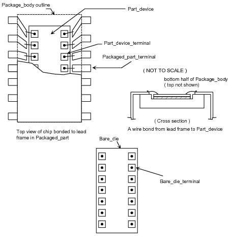
An electrical part is sometimes realized by installing one or more occurrences of die into a container and creating a set
of terminals attached to the die
on the inside and available for external connections on the outside of the container. See
Figure 1
for an illustration of a cutaway view of an electrical component that includes terms related to the Packaged_part Application Object.
Figure 1 — Electrical part exploded assembly detail
NOTE 2
Two Packaged_part models may be exchanged with this part of ISO 10303, depending on usage.
One may support the exchange information that maps the functionality of the Electrical part to the
Bare_die,
or dies, included in the composition of the Packaged_part; and information that maps the terminals of those instances of
Bare_die to the terminals of the Packaged_part.
This mechanism provides maximum flexibility and information exchange and is characterized as a "white box" model.
This model is primarily included in the standard to support design to analysis activities.
Alternatively, one may map the functionality required directly to the Packaged_part terminals, and not populate the
Bare_die.
The alternative is simpler and is characterized as the "black box" model.
NOTE 3
The inclusion of composition elements to help compose a Packaged_part
does not cause the conversion of the Packaged_part to a design view.
EXPRESS specification:
         *)

            SCHEMA Packaged_part_white_box_model_arm;
(*
The following EXPRESS interface statements specify the elements
imported from the ARMs of other application modules.
EXPRESS specification:
*)

            USE FROM
            Bare_die_arm;
               --
            ISO/TS 10303-1650
            USE FROM
            Packaged_part_black_box_model_arm;
               --
            ISO/TS 10303-1710
            USE FROM
            Physical_unit_2d_shape_arm;
               --
            ISO/TS 10303-1726
            USE FROM
            Physical_unit_3d_shape_arm;
               --
            ISO/TS 10303-1727
(*
NOTE 1
The schemas referenced above are specified in the following
part of ISO 10303:
| Bare_die_arm |
ISO/TS 10303-1650 |
| Packaged_part_black_box_model_arm |
ISO/TS 10303-1710 |
| Physical_unit_2d_shape_arm |
ISO/TS 10303-1726 |
| Physical_unit_3d_shape_arm |
ISO/TS 10303-1727 |
NOTE 2
See Annex C,
Figures
C.1, C.2and C.3
for a graphical representation of this schema.
This subclause specifies the ARM type
for this application module. The ARM type and
definition is specified below.
The ppwbm_analytical_model_port_assignment_select type is an extension
of the
analytical_model_port_assignment_select type.
It adds the data
types
Functional_unit_usage_view_terminal_definition, Connection_zone, Part_device_terminal
and
Part_feature
to the list of alternate data types.
NOTE The list of entity data types may be
extended in application modules that use the constructs of
this module.
EXPRESS specification:
            *)

            TYPE
            ppwbm_analytical_model_port_assignment_select =

            EXTENSIBLE

            GENERIC_ENTITY


            SELECT
            BASED_ON
            analytical_model_port_assignment_select
            WITH


               (Functional_unit_usage_view_terminal_definition,
    Connection_zone,
    Part_device_terminal,
    Part_feature);

            END_TYPE;

            (*
This subclause specifies the ARM entities for this
module. Each ARM application entity is an atomic element that
embodies a unique application concept and contains attributes
specifying the data elements of the entity. The ARM
entities and definitions are specified below.
A Device_2d_position is the location in two dimensions of a
Part_device
within a Packaged_part.
EXPRESS specification:
            *)

            ENTITY Device_2d_position;


              placed_device : Part_device;


              transformation : Axis_placement_2d;


              part_shape : Physical_unit_planar_shape_model;


              device_shape : Physical_unit_planar_shape_model;

            END_ENTITY;
(*
Attribute definitions:
placed_device:
specifies a role of the Part_device
for the
Device_2d_position.
transformation:
specifies the Axis_placement_2d
for the
Device_2d_position.
part_shape:
specifies the Physical_unit_planar_shape_model of the
Packaged_part for the
Device_2d_position.
device_shape:
specifies the Physical_unit_planar_shape_model of the
Part_device for the
Device_2d_position.
A Device_3d_position is the location in three dimensions of a
Part_device within a
Packaged_part.
EXPRESS specification:
            *)

            ENTITY Device_3d_position;


              placed_device : Part_device;


              transformation : Axis_placement_3d;


              part_shape : Physical_unit_3d_shape_model;


              device_shape : Physical_unit_3d_shape_model;

            END_ENTITY;
(*
Attribute definitions:
placed_device:
specifies a role of the Part_device
for the
Device_3d_position.
transformation:
specifies the Axis_placement_3d of the
Packaged_part
for the Device_3d_position.
part_shape:
specifies the Physical_unit_3d_shape_model of the
Packaged_part
for the Device_3d_position.
device_shape:
specifies the Physical_unit_3d_shape_model of the
Part_device for the
Device_3d_position.
A Device_terminal_map is the association between a
Part_device_terminal and a
Packaged_part_terminal. A
Device_terminal_map provides the
topological equivalent of a bond wire from the package terminal to the terminal of the installed
Part_device.
EXPRESS specification:
            *)

            ENTITY Device_terminal_map;


              target_terminal : Packaged_part_terminal;


              mapped_device_terminal : Part_device_terminal;
UNIQUE

              UR1: mapped_device_terminal, target_terminal;

            END_ENTITY;
(*
Attribute definitions:
target_terminal:
specifies the targeted
Packaged_part_terminal for the
Device_terminal_map.
mapped_device_terminal:
specifies the Part_device_terminal
from which the association is made to the target_terminal by the
Device_terminal_map.
Formal propositions:
UR1:
The combination of target_terminal and mapped_device_terminal shall be unique within a population of
Device_terminal_map.
A Device_terminal_map_relationship is the association of one
Device_terminal_map to another.
EXPRESS specification:
            *)

            ENTITY Device_terminal_map_relationship;


              relating_device_terminal_map : Device_terminal_map;


              related_device_terminal_map : Device_terminal_map;

            END_ENTITY;
(*
Attribute definitions:
relating_device_terminal_map:
an instance specifies the source
Device_terminal_map in the
Device_terminal_map_relationship.
related_device_terminal_map:
an instance specifies the target
Device_terminal_map in the
Device_terminal_map_relationship. If one element of the relationship is dependent up on the other, this attribute shall be the dependent one.
A Part_device is a specific occurrence of a Bare_die in a
Packaged_part.
EXPRESS specification:
            *)

            ENTITY Part_device;


              defined_packaged_part : Packaged_part;


              included_device : Bare_die;


              item_identification : STRING;
INVERSE

              device_3d_position : SET[0:1] OF Device_3d_position FOR placed_device;

              device_2d_position : SET[0:1] OF Device_2d_position FOR placed_device;
UNIQUE

              UR1: defined_packaged_part, item_identification;

            END_ENTITY;
(*
Attribute definitions:
defined_packaged_part:
specifies the Packaged_part that
contains this Part_device.
included_device:
specifies the Bare_die used to provide the
function of the Part_device.
item_identification:
specifies the string for the Part_device.
The item_identification specifies the name for the reference designation of the
Bare_die instance within the
Packaged_part.
device_3d_position:
specifies an inverse relationship that specifies that the existence of the Part_device
is dependent on the existence of the
Device_3d_position
that specifies the Part_device
as its
placed_device.
There shall be no more than one device_3d_position for a Part_device.
device_2d_position:
specifies an inverse relationship that specifies that the existence of the Part_device
is dependent on the existence of the
Device_2d_position
that specifies the Part_device
as its
placed_device.
There shall be no more than one device_2d_position for a Part_device.
Formal propositions:
UR1:
The combination of defined_packaged_part and item_identification shall be unique within a
population of Part_devices.
A Part_device_terminal is the surface area on an occurrence of a
Bare_die in a
Packaged_part that shall allow access
to the function of an occurrence of the Bare_die. A
Part_device_terminal is included to support detailed modeling and analysis of the internal connection to a
Packaged_part_terminal. No
connection between Part_device_terminals is supported in this part of ISO 10303. Connections between
Bare_die are supported only within
Assembly_module_design_view.
EXPRESS specification:
            *)

            ENTITY Part_device_terminal;


              used_bare_die_terminal : Minimally_defined_bare_die_terminal;


              terminated_device : Part_device;
UNIQUE

              UR1: used_bare_die_terminal, terminated_device;

            END_ENTITY;
(*
Attribute definitions:
used_bare_die_terminal:
specifies the Minimally_defined_bare_die_terminal that shall be used by the
Part_device_terminal.
terminated_device:
specifies the Part_device that has
this
Part_device_terminal.
Formal propositions:
UR1:
The combination of terminated_device and used_bare_die_terminal shall be unique within a
population of Part_device_terminals.
This subclause specifies the ARM
subtype constraints for
this module. Each subtype constraint places constraints on the
possible super-type / subtype instantiations.
The ARM subtype constraints and definitions are
specified below.
The
physical_unit_keepout_shape_model_subtypes
constraint specifies a constraint that applies to instances of subtypes of
Physical_unit_keepout_shape_model.
EXPRESS specification:
            *)
SUBTYPE_CONSTRAINT physical_unit_keepout_shape_model_subtypes FOR Physical_unit_keepout_shape_model;

              ONEOF (Physical_unit_3d_keepout_shape_model,
         Physical_unit_planar_keepout_shape_model);

            END_SUBTYPE_CONSTRAINT;
(*
The
physical_unit_shape_model_subtypes
constraint specifies a constraint that applies to instances of subtypes of
Physical_unit_shape_model.
EXPRESS specification:
            *)
SUBTYPE_CONSTRAINT physical_unit_shape_model_subtypes FOR Physical_unit_shape_model;

              ONEOF (Physical_unit_3d_shape_model,
         Physical_unit_planar_shape_model);

            END_SUBTYPE_CONSTRAINT;
(*
         *)

         END_SCHEMA;  -- Packaged_part_white_box_model_arm
(*
© ISO 2014 — All rights reserved