|
|
Application module:
Interconnect module usage view |
ISO/TS 10303-1686:2018-11(E)
© ISO
|
This clause specifies the information requirements for the
Interconnect module usage view
application module. The information requirements are specified as the
Application Reference Model (ARM) of this application module.
NOTE 1 A graphical representation of the information
requirements is given in
Annex C.
NOTE 2 The mapping specification is specified in
5.1. It shows how
the information requirements are met by using common resources and
constructs defined or imported in the MIM schema of this application
module.
This clause defines the information requirements to which implementations shall
conform using the EXPRESS language as defined in ISO 10303-11.
The following begins the
Interconnect_module_usage_view_arm
schema and identifies the necessary external references.
EXPRESS specification:
         *)

            SCHEMA Interconnect_module_usage_view_arm;
(*
The following EXPRESS interface statements specify the elements
imported from the ARMs of other application modules.
EXPRESS specification:
*)

            USE FROM
            Characteristic_arm;
               --
            ISO/TS 10303-1654
            USE FROM
            Functional_assignment_to_part_arm;
               --
            ISO/TS 10303-1674
            USE FROM
            Functional_usage_view_arm;
               --
            ISO/TS 10303-1705
            USE FROM
            Geometric_tolerance_arm;
               --
            ISO/TS 10303-1051
            USE FROM
            Non_feature_shape_element_arm;
               --
            ISO/TS 10303-1706
            REFERENCE FROM
            Requirement_decomposition_arm

               --
            ISO/TS 10303-1740
  (get_rvd);

(*
NOTE 1
The schemas referenced above are specified in the following
part of ISO 10303:
| Characteristic_arm |
ISO/TS 10303-1654 |
| Functional_assignment_to_part_arm |
ISO/TS 10303-1674 |
| Functional_usage_view_arm |
ISO/TS 10303-1705 |
| Geometric_tolerance_arm |
ISO/TS 10303-1051 |
| Non_feature_shape_element_arm |
ISO/TS 10303-1706 |
| Requirement_decomposition_arm |
ISO/TS 10303-1740 |
NOTE 2
See Annex C,
Figures
C.1, C.2and C.3
for a graphical representation of this schema.
This subclause specifies the ARM type
for this application module. The ARM type and
definition is specified below.
The cavity_reference_select type allows for the designation of the data
types
Interconnect_module_primary_surface, and Interconnect_module_secondary_surface.
EXPRESS specification:
            *)

            TYPE
            cavity_reference_select =


            SELECT

               (Interconnect_module_primary_surface,
    Interconnect_module_secondary_surface);

            END_TYPE;

            (*
This subclause specifies the ARM entities for this
module. Each ARM application entity is an atomic element that
embodies a unique application concept and contains attributes
specifying the data elements of the entity. The ARM
entities and definitions are specified below.
An Interconnect_module_cavity_surface is a type of
Interconnect_module_surface_feature.
When this information is represented by a planar shape, the interpretation is to be that the planar shape represents a projection
of
the maximum extent of the Interconnect_module_cavity_surface onto the planar shape.
The Interconnect_module_cavity_surface forms an internal physical
boundary of the interconnect substrate. The Interconnect_module_cavity_surface is represented by a closed curve in two dimensional representations and by a
manifold surface in three dimensional representations.
NOTE 1
Care should be taken in pre-processors to ensure that both two and three dimensional representations adhere to reasonable
industrial practice regarding
tangential intersections of curves and straight line segments.
NOTE 2
The Interconnect_module_cavity_surface is represented as a simple or complex
Cutout
in the design view.
EXPRESS specification:
            *)

            ENTITY Interconnect_module_cavity_surface

              SUBTYPE OF (Interconnect_module_surface_feature);


              reference_surface : cavity_reference_select;
WHERE

              WR1: SELF :<>: reference_surface;

              WR2: SIZEOF(QUERY(ucur <* USEDIN(SELF,
            'PART_FEATURE_LOCATION_ARM.USAGE_CONCEPT_USAGE_RELATIONSHIP.' +
            'ASSOCIATED_USAGE') | NOT
            ('CONSTRUCTIVE_SOLID_GEOMETRY_2D_ARM.SINGLE_BOUNDARY_CSG_2D_MODEL' IN TYPEOF(ucur.associated_shape_definition))
            )) = 0;

            END_ENTITY;
(*
Attribute definitions:
reference_surface:
specifies the
cavity_reference_select
for the Interconnect_module_cavity_surface.
Formal propositions:
WR1:
The reference_surface shall not be this Interconnect_module_cavity_surface.
WR2:
Only a
Single_boundary_csg_2d_model
shall be used as the shape model for an Interconnect_module_cavity_surface.
An Interconnect_module_cutout_segment_surface is a type of
Interconnect_module_surface_feature.
An Interconnect_module_cutout_segment_surface identifies a segment of the cutout surface of the
Layered_interconnect_module_design_view
for fabrication and assembly purposes.
The curve representing this concept in two dimensional representations shall be open.
The surface representing this concept in three dimensional representations shall be non-manifold.
Pre-processors shall adhere to the requirement that the boundary this segment is contributing to shall be closed.
NOTE
This data is usage view contextual data.
If a design view is provided and this member of Interconnect_module_cutout_segment_surface is specified by a member of
Stratum_concept_to_physical_usage_view_assignment
in the role of
defined_part_feature,
a member of
Interconnect_module_cutout_segment_surface
shall be the only possibilities permitted to be specified for the role of
assigned_design_object
for that member of
Stratum_concept_to_physical_usage_view_assignment.
EXPRESS specification:
            *)

            ENTITY Interconnect_module_cutout_segment_surface

              SUBTYPE OF (Interconnect_module_surface_feature);


              composed_surface : Interconnect_module_cutout_surface;


              start_vertex : Edge_segment_vertex;


              end_vertex : Edge_segment_vertex;
WHERE

              WR1: start_vertex :<>: end_vertex;

            END_ENTITY;
(*
Attribute definitions:
composed_surface:
specifies the
Interconnect_module_cutout_surface
for an Interconnect_module_cutout_segment_surface.
start_vertex:
specifies the initial
Edge_segment_vertex
for an Interconnect_module_cutout_segment_surface.
end_vertex:
specifies the final
Edge_segment_vertex
for an Interconnect_module_cutout_segment_surface.
Formal propositions:
WR1:
The end_vertex shall not be the start_vertex.
An Interconnect_module_cutout_surface is a type of a
Interconnect_module_surface_feature
that is completely through the material of the
Layered_interconnect_module_design_view
in the
Interconnect_module_usage_view.
When this information is represented by a planar shape, the interpretation is to be that the planar shape represents a projection
of
the maximum extent of the Interconnect_module_cutout_surface onto the planar shape.
The Interconnect_module_cutout_surface forms an internal physical
boundary of the interconnect substrate. The Interconnect_module_cutout_surface is represented by a closed curve in two dimensional representations and by a
manifold surface in three dimensional representations.
NOTE
Care should be taken in pre-processors to ensure that both two and three dimensional representations adhere to reasonable
industrial practice regarding
tangential intersections of curves and straight line segments.
EXPRESS specification:
            *)

            ENTITY Interconnect_module_cutout_surface

              SUBTYPE OF (Interconnect_module_surface_feature);
WHERE

              WR1: SIZEOF(QUERY(ucur <* USEDIN(SELF,
            'PART_FEATURE_LOCATION_ARM.USAGE_CONCEPT_USAGE_RELATIONSHIP.' +
            'ASSOCIATED_USAGE') | NOT
            ('CONSTRUCTIVE_SOLID_GEOMETRY_2D_ARM.SINGLE_BOUNDARY_CSG_2D_MODEL' IN
            TYPEOF(ucur.associated_shape_definition)))) = 0;

            END_ENTITY;
(*
Formal propositions:
WR1:
Only a
Single_boundary_csg_2d_model
shall be used as the shape model for an Interconnect_module_cutout_surface.
An Interconnect_module_edge_segment_surface is a type of
Interconnect_module_surface_feature.
An Interconnect_module_edge_segment_surface identifies a segment of the edge surface of the
Layered_interconnect_module_design_view
for fabrication and assembly purposes.
The curve representing this concept in two dimensional representations shall be open.
The surface representing this concept in three dimensional representations shall be non-manifold.
Pre-processors shall adhere to the requirement that the boundary this segment is contributing to shall be closed.
NOTE
This data is usage view contextual data.
If a design view is provided and this member of Interconnect_module_edge_segment_surface is specified by a member of
Stratum_concept_to_physical_usage_view_assignment
in the role of
defined_part_feature,
a member of
Interconnect_module_edge_segment
or a member of
Plated_interconnect_module_edge_segment
shall be the only possibilities permitted to be specified for the role of
assigned_design_object
for that member of
Stratum_concept_to_physical_usage_view_assignment.
EXPRESS specification:
            *)

            ENTITY Interconnect_module_edge_segment_surface

              SUBTYPE OF (Interconnect_module_surface_feature);


              composed_surface : Interconnect_module_edge_surface;


              start_vertex : Edge_segment_vertex;


              end_vertex : Edge_segment_vertex;
WHERE

              WR1: start_vertex :<>: end_vertex;

            END_ENTITY;
(*
Attribute definitions:
composed_surface:
specifies the
Interconnect_module_edge_surface
for the Interconnect_module_edge_segment_surface.
start_vertex:
specifies the initial
Edge_segment_vertex
for the Interconnect_module_edge_segment_surface.
end_vertex:
specifies the final
Edge_segment_vertex
for the Interconnect_module_edge_segment_surface.
Formal propositions:
WR1:
The end_vertex shall not be the start_vertex.
An Interconnect_module_edge_surface is a type of
Interconnect_module_surface_feature.
An Interconnect_module_edge_surface identifies the edge surface of the
Layered_interconnect_module_design_view
for fabrication and assembly purposes.
When this information is represented by a planar shape, the interpretation is to be that the planar shape represents a projection
of
the maximum extent of the Interconnect_module_edge_surface onto the planar shape. The Interconnect_module_edge_surface forms an outer physical
boundary of the interconnect substrate. The Interconnect_module_edge_surface is represented by a closed curve in two dimensional representations and by a
manifold surface in three dimensional representations.
NOTE
Care should be taken in pre-processors to ensure that both two and three dimensional representations adhere to reasonable
industrial practice regarding
tangential intersections of curves and straight line segments.
EXPRESS specification:
            *)

            ENTITY Interconnect_module_edge_surface

              SUBTYPE OF (Interconnect_module_surface_feature);
WHERE

              WR1: SIZEOF(QUERY(ucur <* USEDIN(SELF,
            'PART_FEATURE_LOCATION_ARM.USAGE_CONCEPT_USAGE_RELATIONSHIP.' +
            'ASSOCIATED_USAGE') | NOT
            ('CONSTRUCTIVE_SOLID_GEOMETRY_2D_ARM.SINGLE_BOUNDARY_CSG_2D_MODEL' IN
            TYPEOF(ucur.associated_shape_definition)))) = 0;

            END_ENTITY;
(*
Formal propositions:
WR1:
Only a
Single_boundary_csg_2d_model
shall be used as the shape model for an Interconnect_module_edge_surface.
An Interconnect_module_interface_terminal is a type of Interconnect_module_terminal.
The functionality is provided by accessing a pattern on the interconnect substrate designed to interface with external conductors.
EXAMPLE
The tinned surface of a Land is designed to accept a surface mount lead. The tinned surface of the Land would be bound to the Interconnect_module_interface_terminal by
a feature to usage view assignment relationship.
NOTE
The distinction of an interface terminal for a substrate only exists to support classification of an application of a substrate
as being a product application where the substrate is delivered as a discrete product
versus the application where the design of the substrate is consumed in another substrate design and is not separately supplied
as a product.
EXPRESS specification:
            *)

            ENTITY Interconnect_module_interface_terminal

              SUBTYPE OF (Interconnect_module_terminal);
DERIVE

              SELF\Part_terminal.interface_or_join_terminal : interface_or_join_terminal_enumeration := interface_or_join_terminal_enumeration.interface_terminal;

            END_ENTITY;
(*
Attribute definitions:
interface_or_join_terminal:
the terminal shall be an
interface_terminal.
An Interconnect_module_primary_surface is a type of Interconnect_module_surface_feature.
An Interconnect_module_primary_surface identifies the primary surface of the Layered_interconnect_module_design_view for fabrication and assembly purposes. A member of Stratum_concept_to_physical_usage_view_assignment shall be populated in order to associate this object to the primary Stratum if a design view of the substrate is
included in the data. An Interconnect_module_primary_surface is an approximation of the real primary surface.
NOTE
It is not usually the case that the physical material visible on the surface of the substrate or pcb is the same material
as that of the primary
Stratum.
The level of information provided by this object is usually sufficient for assembly purposes,
but will be in error by the thickness of the
Stratum
above the primary
Stratum.
That Stratum
will be the material of at least part of the surface of the substrate.
Full three-dimensional representation capability and location of individual
Interconnect_module_component_terminal
associated by
Assembly_joint
to the component feature being assembled to the substrate is required to represent exactly the mating conditions.
EXPRESS specification:
            *)

            ENTITY Interconnect_module_primary_surface

              SUBTYPE OF (Interconnect_module_surface_feature);

            END_ENTITY;
(*
An Interconnect_module_secondary_surface is a type of Interconnect_module_surface_feature.
An Interconnect_module_secondary_surface identifies the secondary surface of the Layered_interconnect_module_design_view for fabrication and assembly purposes.
If a design view is populated, and correlation to a Stratum is provided,
the Stratum associated with this member of Interconnect_module_primary_surface shall be the last Stratum
in the design.
NOTE
The
Stratum_concept_to_physical_usage_view_assignment,
and Stratum_surface provide supporting data needed to resolve the position of the Stratum in the design. Because the secondary surface is derived structurally from the primary Stratum, there is no approximation made in the description.
EXPRESS specification:
            *)

            ENTITY Interconnect_module_secondary_surface

              SUBTYPE OF (Interconnect_module_surface_feature);

            END_ENTITY;
(*
An Interconnect_module_surface_feature is a type of Part_feature.
Each Interconnect_module_surface_feature is either an
Interconnect_module_cavity_surface,
an
Interconnect_module_cutout_segment_surface,
an
Interconnect_module_cutout_surface,
an
Interconnect_module_secondary_surface,
an
Interconnect_module_primary_surface,
an
Interconnect_module_edge_surface,
or an
Interconnect_module_edge_segment_surface.
An Interconnect_module_surface_feature identifies a surface of the Layered_interconnect_module_design_view for fabrication and
assembly purposes, particular to support Component_2d_location.
EXPRESS specification:
            *)

            ENTITY Interconnect_module_surface_feature

              ABSTRACT SUPERTYPE

            OF (ONEOF (Interconnect_module_cavity_surface,
                                Interconnect_module_cutout_segment_surface,
                                Interconnect_module_cutout_surface,
                                Interconnect_module_secondary_surface,
                                Interconnect_module_primary_surface,
                                Interconnect_module_edge_surface,
                                Interconnect_module_edge_segment_surface))

              SUBTYPE OF (Part_feature);


              SELF\Part_feature.associated_definition : Layered_interconnect_module_usage_view;

            END_ENTITY;
(*
Attribute definitions:
associated_definition:
specifies a role of the Interconnect_module_usage_view for
the Interconnect_module_surface_feature.
An Interconnect_module_terminal is a type of
Part_terminal.
The Interconnect_module_terminal identification is provided by the
element_name
attribute inherited from Shape_element.
The string may include a substring that indicates to a person the connector the Interconnect_module_terminal is associated with.
An Interconnect_module_terminal may be referenced by a member of
Part_connected_terminals_definition
to identify a connection requirement for the
Layered_interconnect_module_design_view.
NOTE 1
The Interconnect_module_terminal may be an
Interconnect_module_stratum_based_terminal
but this fact is not structurally captured in this application object due to the need to require that the Interconnect_module_terminal shall be one of the two specified subtypes.
NOTE 2
This part of ISO 10303 does not explicitly model, in a usage view, the relationship of a printed connector to an
Layered_interconnect_module_design_view
in addition to the associated_definition relationship provided in this Application Object.
EXAMPLE
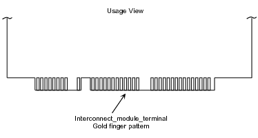
Figure 1
illustrates a detail of a usage view that shows an Interconnect_module_terminal that is a part of an edge finger connector.
Figure 1 — Interconnect_module_terminal
EXPRESS specification:
            *)

            ENTITY Interconnect_module_terminal

              SUBTYPE OF (Part_terminal);


              connection_area :
            OPTIONAL
            SET[1:?] OF Connection_zone_in_usage_view;


              SELF\Part_feature.associated_definition : Layered_interconnect_module_usage_view;

            END_ENTITY;
(*
Attribute definitions:
connection_area:
specifies a role of the
Connection_zone_in_usage_view
for the Interconnect_module_terminal. There may be more than one
Connection_zone_in_usage_view
for an Interconnect_module_terminal. The value of this attribute need not be specified.
If the source system contains the data, then the data shall be provided.
NOTE 3
The Usage_concept_usage_relationship
specified by the terminal or mounting feature may be the same
Usage_concept_usage_relationship
that is specified by the associated
Connection_zone.
In this case the whole terminal is the
Connection_zone.
associated_definition:
specifies a role of the
Interconnect_module_usage_view
for the Interconnect_module_terminal.
An Interconnect_module_terminal_surface_constituent_relationship is a type of
Shape_element_relationship.
EXPRESS specification:
            *)

            ENTITY Interconnect_module_terminal_surface_constituent_relationship

              SUBTYPE OF (Shape_element_relationship);


              SELF\Shape_element_relationship.relating : Interconnect_module_surface_feature;


              SELF\Shape_element_relationship.related : Interconnect_module_terminal;

            END_ENTITY;
(*
Attribute definitions:
relating:
one of the instances of Interconnect_module_surface_feature
that is part of the relationship.
related:
the other instance of Interconnect_module_terminal
that is part of the relationship. If one element of the relationship is dependent upon the other, this attribute shall be
the dependent one.
An Interconnect_module_usage_view is a type of
Part_usage_view
to support the application of an interconnect in an assembly. Predefined support for typical
features found in industrial practice is provided.
An Interconnect_module_usage_view may be a
Layered_interconnect_module_usage_view.
Either the thickness_over_dielectric_requirement or the thickness_over_metal_requirement shall be provided.
If both the thickness_over_dielectric_requirement and the thickness_over_metal_requirement are provided,
the thickness_over_metal_requirement shall be greater than the thickness_over_dielectric_requirement.
An Interconnect_module_usage_view provides physical shape and logical connection identification and location information for an interconnect.
EXPRESS specification:
            *)

            ENTITY Interconnect_module_usage_view

              SUPERTYPE OF (Layered_interconnect_module_usage_view)

              SUBTYPE OF (Part_usage_view);

            END_ENTITY;
(*
A Layered_interconnect_module_usage_view is a type of
Interconnect_module_usage_view
that provides the information necessary to include the Layered_interconnect_module_design_view in its next higher level assembly for design and some simulation purposes, but may not include sufficient information to
reproduce the Pcb.
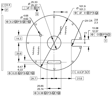
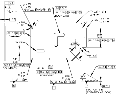
EXAMPLE
Some of the information in figures 2 and
3 may be included in a usage view; especially that information that communicate fit tolerances.
Figure 2 — Circular interconnect tolerances
Figure 3 — Complex interconnect tolerances
EXPRESS specification:
            *)

            ENTITY Layered_interconnect_module_usage_view

              SUBTYPE OF (Interconnect_module_usage_view);


              thickness_over_dielectric_requirement :
            OPTIONAL
            Length_tolerance_characteristic;


              thickness_over_metal_requirement :
            OPTIONAL
            Length_tolerance_characteristic;


              located_thickness_requirement :
            OPTIONAL
            SET[1:?] OF Located_interconnect_module_thickness_requirement;


              implemented_function :
            OPTIONAL
            Functional_unit_usage_view;
WHERE

              WR1: SIZEOF(QUERY(pf <* USEDIN(SELF,
            'INTERCONNECT_MODULE_USAGE_VIEW_ARM.INTERCONNECT_MODULE_SURFACE_FEATURE.ASSOCIATED_DEFINITION') | ('INTERCONNECT_MODULE_USAGE_VIEW_ARM.'
            + 'INTERCONNECT_MODULE_PRIMARY_SURFACE' IN TYPEOF(pf)))) <= 1;

              WR2: SIZEOF(QUERY(pf <* USEDIN(SELF,
            'INTERCONNECT_MODULE_USAGE_VIEW_ARM.INTERCONNECT_MODULE_SURFACE_FEATURE.ASSOCIATED_DEFINITION') | ('INTERCONNECT_MODULE_USAGE_VIEW_ARM.'
            + 'INTERCONNECT_MODULE_SECONDARY_SURFACE' IN TYPEOF(pf)))) <= 1;

              WR3: SIZEOF(QUERY(pf <* USEDIN(SELF,
            'INTERCONNECT_MODULE_USAGE_VIEW_ARM.INTERCONNECT_MODULE_SURFACE_FEATURE.ASSOCIATED_DEFINITION') | ('INTERCONNECT_MODULE_USAGE_VIEW_ARM.'
            + 'INTERCONNECT_MODULE_EDGE_SURFACE' IN TYPEOF(pf)))) <= 1;

              WR4: NOT EXISTS(SELF\Product_view_definition.additional_characterization);

            END_ENTITY;
(*
Attribute definitions:
thickness_over_dielectric_requirement:
specifies the role of the
Length_tolerance_characteristic
for the Layered_interconnect_module_usage_view.
The value of this attribute need not be specified.
thickness_over_metal_requirement:
specifies the role of the
Length_tolerance_characteristic
for the Layered_interconnect_module_usage_view.
The value of this attribute need not be specified.
located_thickness_requirement:
specifies the role of the
Located_interconnect_module_thickness_requirement
for the Layered_interconnect_module_usage_view.
There shall exist more than one
Located_interconnect_module_thickness_requirement
for the Layered_interconnect_module_usage_view.
The value of this attribute need not be specified.
implemented_function:
specifies the role of the
Functional_unit_usage_view
for the Layered_interconnect_module_usage_view.
The value of this attribute need not be specified.
Formal propositions:
WR1:
No more than one
Interconnect_module_primary_surface
shall reference a Layered_interconnect_module_usage_view.
WR2:
No more than one
Interconnect_module_secondary_surface
shall reference a Layered_interconnect_module_usage_view.
WR3:
No more than one
Interconnect_module_edge_surface
shall reference a Layered_interconnect_module_usage_view.
WR4:
The
additional_characterization
shall not be populated.
A Located_interconnect_module_thickness_requirement is a definition that relates
a specific location with a thickness requirement for an interconnect substrate.
EXPRESS specification:
            *)

            ENTITY Located_interconnect_module_thickness_requirement;


              reference_location : Axis_placement;


              thickness_requirement : Length_tolerance_characteristic;
INVERSE

              design : SET[1:?] OF Layered_interconnect_module_usage_view FOR located_thickness_requirement;
UNIQUE

              UR1: design, reference_location;

            END_ENTITY;
(*
Attribute definitions:
reference_location:
specifies the role of the
Axis_placement
for the Located_interconnect_module_thickness_requirement.
thickness_requirement:
specifies the
Length_tolerance_characteristic
that is the bound for the Located_interconnect_module_thickness_requirement.
design:
an inverse relationship that specifies that the existence of the Located_interconnect_module_thickness_requirement is dependent on the existence of the
Layered_interconnect_module_usage_view
that specifies the Located_interconnect_module_thickness_requirement as its
located_thickness_requirement.
There shall be one or more
Layered_interconnect_module_usage_view for a
Located_interconnect_module_thickness_requirement.
Formal propositions:
UR1:
The combination of the design and the reference_location shall be unique within a population of
Located_interconnect_module_thickness_requirements.
         *)

         END_SCHEMA;  -- Interconnect_module_usage_view_arm
(*
© ISO 2018 — All rights reserved


