|
|
Application module:
Assembly module with interconnect component |
ISO/TS 10303-1643:2018-11(E)
© ISO
|
This clause specifies the information requirements for the
Assembly module with interconnect component
application module. The information requirements are specified as the
Application Reference Model (ARM) of this application module.
NOTE 1 A graphical representation of the information
requirements is given in
Annex C.
NOTE 2 The mapping specification is specified in
5.1. It shows how
the information requirements are met by using common resources and
constructs defined or imported in the MIM schema of this application
module.
This clause defines the information requirements to which implementations shall
conform using the EXPRESS language as defined in ISO 10303-11.
The following begins the
Assembly_module_with_interconnect_component_arm
schema and identifies the necessary external references.
EXPRESS specification:
         *)

            SCHEMA Assembly_module_with_interconnect_component_arm;
(*
The following EXPRESS interface statements specify the elements
imported from the ARMs of other application modules.
EXPRESS specification:
*)

            USE FROM
            Assembly_module_with_packaged_component_arm;
               --
            ISO/TS 10303-1829
            USE FROM
            Bare_die_arm;
               --
            ISO/TS 10303-1650
            USE FROM
            Interconnect_module_usage_view_arm;
               --
            ISO/TS 10303-1686
            USE FROM
            Interface_component_arm;
               --
            ISO/TS 10303-1691
            USE FROM
            Layered_interconnect_simple_template_arm;
               --
            ISO/TS 10303-1718
(*
NOTE 1
The schemas referenced above are specified in the following
part of ISO 10303:
| Assembly_module_with_packaged_component_arm |
ISO/TS 10303-1829 |
| Bare_die_arm |
ISO/TS 10303-1650 |
| Interconnect_module_usage_view_arm |
ISO/TS 10303-1686 |
| Interface_component_arm |
ISO/TS 10303-1691 |
| Layered_interconnect_simple_template_arm |
ISO/TS 10303-1718 |
NOTE 2
See Annex C,
Figures
C.1, C.2and C.3
for a graphical representation of this schema.
This subclause specifies the ARM type
for this application module. The ARM type and
definition is specified below.
The conductive_interconnect_terminal_or_interconnect_component_join_terminal type allows for the designation of the data
types
Interconnect_component_interface_terminal, Interconnect_component_join_terminal, and Movable_packaged_component_join_terminal.
EXPRESS specification:
            *)

            TYPE
            conductive_interconnect_terminal_or_interconnect_component_join_terminal =


            SELECT

               (Interconnect_component_interface_terminal,
    Interconnect_component_join_terminal,
    Movable_packaged_component_join_terminal);

            END_TYPE;

            (*
This subclause specifies the ARM entities for this
module. Each ARM application entity is an atomic element that
embodies a unique application concept and contains attributes
specifying the data elements of the entity. The ARM
entities and definitions are specified below.
An Assembly_connection_zone_position_relationship is the association between a geometric model of an
Assembly_module_design_view,
as a target, and a geometric model of a
Connection_zone_in_design_view,
as the source.
This relationship positions and orients the source into the target using a transformation.
The source is a model of a connection area associated with a design specific terminal created in the assembly.
NOTE 1
There can be only one terminal that uses the
Connection_zone_in_design_view
referenced so there is no need to reference the terminal in this relationship.
NOTE 2
The terminal that uses the
Connection_zone_in_design_view
is a terminal of a component in the assembly.
EXPRESS specification:
            *)

            ENTITY Assembly_connection_zone_position_relationship;


              associating_design_view_shape : Geometric_model;


              associated_usage : Connection_zone_in_design_view;


              associated_connection_zone_shape_definition : Geometric_model;


              associated_usage_placement : Axis_placement;


              associating_design_view : Assembly_module_design_view;

            END_ENTITY;
(*
Attribute definitions:
associating_design_view_shape:
specifies one role of the
Geometric_model
for the Assembly_connection_zone_position_relationship.
associated_usage:
specifies the role of the
Connection_zone_in_design_view
for the Assembly_connection_zone_position_relationship.
associated_connection_zone_shape_definition:
specifies one role of the
Geometric_model
for the Assembly_connection_zone_position_relationship.
associated_usage_placement:
specifies the role of the
Axis_placement
for the Assembly_connection_zone_position_relationship.
associating_design_view:
specifies the role of the
Assembly_module_design_view
for the Assembly_connection_zone_position_relationship.
A Bare_die_component is a type of
Physical_component
and a type of
Single_instance
that is defined by a
Bare_die.
EXPRESS specification:
            *)

            ENTITY Bare_die_component

              SUBTYPE OF (Physical_component, Single_instance);


              SELF\Definition_based_product_occurrence.derived_from : Bare_die;
WHERE

              WR1: NOT EXISTS(SELF\Product_view_definition.name);

            END_ENTITY;
(*
Attribute definitions:
derived_from:
specifies the role of the
Bare_die
for the Bare_die_component.
Formal propositions:
WR1:
The
name
shall not be populated.
A Bare_die_component_terminal is a type of
Physical_component_terminal
that is an instance of a
Bare_die_terminal.
The Bare_die_component_terminal is the area on the bare die instance onto which an enterprise will place bond wires,
thereby joining the active areas on the die instance to the next level of assembly. It is not necessarily the shape of the
land itself on the die.
EXPRESS specification:
            *)

            ENTITY Bare_die_component_terminal

              SUBTYPE OF (Physical_component_terminal);


              SELF\Component_feature.definition : Bare_die_terminal;


              SELF\Component_feature.associated_definition : Bare_die_component;
WHERE

              WR1: NOT EXISTS(SELF\Shape_element.description);

            END_ENTITY;
(*
Attribute definitions:
definition:
specifies the role of the
Bare_die_terminal
for the Bare_die_component_terminal.
associated_definition:
specifies the
Bare_die_component
to which the Bare_die_component_terminal provides electrical access.
Formal propositions:
WR1:
The
description
shall not be populated.
A Component_overlap_relationship is the relationship between
one component and another in their next assembly, with respect to the physical overlap between them.
This overlap is often derived from the mechanism requirements of the factory equipment that assembles the
components to their next assembly. The sequence of assembly is established by the
previously_placed_component and the current_component, in turn, and the minimum clearance between
the two components is taken into consideration during assembly.
EXPRESS specification:
            *)

            ENTITY Component_overlap_relationship;


              previously_placed_component : Next_assembly_usage;


              current_component : Next_assembly_usage;


              added_clearance : Length_tolerance_characteristic;

            END_ENTITY;
(*
Attribute definitions:
previously_placed_component:
specifies the
Next_assembly_usage,
of the component previously placed, for the Component_overlap_relationship.
current_component:
specifies the
Next_assembly_usage,
of the component to be placed next, for the Component_overlap_relationship.
added_clearance:
specifies the
Length_tolerance_characteristic
of the distance between the current_component and the previously_placed_component for the Component_overlap_relationship.
A Design_view_terminal_component_shape_relationship is the association between the following pairs where the individual relationship is a (source,target) pair:
(Interconnect_component_join_terminal, Physical_component),
(Interconnect_component_interface_terminal, Physical_component),
(Movable_packaged_component_join_terminal,
Packaged_component).
This relationship positions and orients the geometric model of the source into the model of the target using an item defined
transformation that uses two placements, one in the source
and one in the target to define the transformation. The target is the geometric model of a component in an assembly and is
not the geometric model of the component in a library (although it may be a copy)
and is not the geometric model of the assembly. Therefore the transformation is local to the component geometric model.
An Interconnect_component_join_terminal
shall not be associated with a
Packaged_component.
An Interconnect_component_interface_terminal
shall not be associated with a
Packaged_component.
A
Movable_packaged_component_join_terminal
shall only be associated with a
Packaged_component.
EXPRESS specification:
            *)

            ENTITY Design_view_terminal_component_shape_relationship;


              associating_component_shape : Geometric_model;


              source_placement : Axis_placement;


              associated_usage : conductive_interconnect_terminal_or_interconnect_component_join_terminal;


              associated_terminal_shape_definition : Geometric_model;


              associated_usage_placement : Axis_placement;

            END_ENTITY;
(*
Attribute definitions:
associating_component_shape:
specifies the
Geometric_model,
that is the shape of the component in the design geometric model.
source_placement:
specifies the
Axis_placement
that is the source placement for the Design_view_terminal_component_shape_relationship.
associated_usage:
specifies either the
Interconnect_component_join_terminal,
or the
Movable_packaged_component_join_terminal,
or the Interconnect_component_interface_terminal
that is the source item for the Design_view_terminal_component_shape_relationship.
associated_terminal_shape_definition:
specifies the
Geometric_model
that is the source shape for the Design_view_terminal_component_shape_relationship.
associated_usage_placement:
specifies the
Axis_placement
that is the target for the Design_view_terminal_component_shape_relationship.
An Interconnect_component_interface_terminal is a type of
Physical_component_interface_terminal
that represents some aspect of a generic
Assembly_component
participate in a connection for an assembly.
The Interconnect_component_interface_terminal is defined in-situ. There is no
Part_feature
associated with it.
EXAMPLE 1
An example of an Interconnect_component_interface_terminal is a portion of a mechanical conductive fastener that attaches a
flexible wire lead to the pcb.
The portion that is the Interconnect_component_interface_terminal is the
portion that is not attached to the pcb but is attached to the wire lead.
EXAMPLE 2
A plain wire is considered to be an interconnect component. The Interconnect_component_interface_terminal is located at the opposite end of the wire from that defined for the same wire in
Interconnect_component_join_terminal.
EXPRESS specification:
            *)

            ENTITY Interconnect_component_interface_terminal

              SUBTYPE OF (Physical_component_interface_terminal);


              connection :
            OPTIONAL
            Connection_zone_in_design_view;
WHERE

              WR1: NOT EXISTS(SELF\Shape_element.description);

            END_ENTITY;
(*
Attribute definitions:
connection:
specifies the role of the
Connection_zone_in_design_view
for the Interconnect_component_interface_terminal. The value of this attribute need not be specified.
Formal propositions:
WR1:
The
description
shall not be populated.
An Interconnect_component_join_terminal is a type of
Physical_component_terminal
that represents some aspect of a generic
Assembly_component
participating in a connection for an assembly.
The Interconnect_component_join_terminal is defined in-situ.
EXAMPLE 1
An example of an Interconnect_component_join_terminal is a portion of a mechanical conductive fastener that attaches a flexible
wire lead to the pcb.
The portion that is the Interconnect_component_join_terminal is the portion that is directly connected to the pcb.
EXAMPLE 2
A plain wire is considered to be an interconnect component.
EXPRESS specification:
            *)

            ENTITY Interconnect_component_join_terminal

              SUBTYPE OF (Physical_component_terminal);


              connection_area :
            OPTIONAL
            SET[1:1] OF Connection_zone_in_design_view;


              SELF\Component_feature.associated_definition : Physical_component;
WHERE

              WR1: NOT EXISTS(SELF\Shape_element.description);

              WR2: NOT EXISTS(SELF\Component_feature.definition) OR
            NOT( 'FUNCTIONAL_ASSIGNMENT_TO_PART_ARM.PART_TERMINAL' IN TYPEOF(SELF\Component_feature.definition));

            END_ENTITY;
(*
Attribute definitions:
connection_area:
specifies the role of the
Connection_zone_in_design_view
for the Interconnect_component_join_terminal. There may be one Connection_zone_in_design_view for the Interconnect_component_join_terminal.
The value of this attribute need not be specified. If the source system contains the data, then the data shall be provided.
associated_definition:
specifies the role of the
Physical_component
for the Interconnect_component_join_terminal.
Formal propositions:
WR1:
The
description
shall not be populated.
WR2:
If the definition is provided, it shall not be a part terminal.
An Interconnect_module_component is a type of
Physical_component
and a type of
Single_instance.
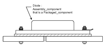
EXAMPLE
Here
Figure 1
illustrates a detail of an assembly drawing that shows the
Assembly_component
in relation to a cross-sectional view of the
Interconnect_module_component.
Figure 2
illustrates a complete assembly showing multiple
Assembly_component.
Figure 1 — Assembly component
Figure 2 — Part design view with an interconnect module component
NOTE 1
The Interconnect_module_component can be, for example, a circuit board in an assembly.
Alternatively, it could be the substrate for a multi-chip module.
This entity is included specifically so that the assembly design definition can be queried
directly to determine which component in the assembly is the substrate. The
Interconnect_module_component is likely the target of connectivity
requirement information as allocated to various components.
An Interconnect_module_component does not include all the internal details of the
design of the
Interconnect_module_design_view.
NOTE 2
An
Assembly_component
may be assembled onto an
Interconnect_module_component
in the realization of an
Assembly_module_design_view.
An
Assembly_component
may be an occurrence of an
Assembly_module_usage_view.
An
Assembly_component
may be an occurrence of an
Interconnect_module_usage_view.
For the purposes of this model, the current interpretation is to treat an embedded discrete component as a
Packaged_component.
The Interconnect_module_component_terminal
that mates with the
Packaged_component_join_terminal
of the embedded component is not visible when the Assembly_module_design_view
is assembled, but the
Interconnect_module_component_terminal
is still logically the interface to the
Interconnect_module_component
for the embedded component.
NOTE 3
A discrete component that is installed or embedded during part of the sequential manufacturing process for an interconnect
product
is considered to be an
Assembly_component
since the form of the component is not realized
during the sequential manufacturing process.
NOTE 4
A Template_definition
occurrence is not permitted in an assembly definition.
NOTE 5
An
Assembly_component
may be a floor-planning symbol if the definition is an
Assembly_module_design_view
or an
Interconnect_module_design_view.
If the
Assembly_component
is used in this manner, then the actual components will be included in the design in a later
iteration that results from including the detailed components from the
Assembly_module_design_view
or
Interconnect_module_design_view
using a computer processor.
The processor may choose to support traceability by using the
Component_feature_to_physical_usage_view_assignment
to specify what component of the
Assembly_module_design_view
or
Interconnect_module_design_view
corresponds to the component in the design.
NOTE 6
Planned parameters may be assigned to
Assembly_component
by the parameter assignment to
Assembly_component_relationship
by the
Planned_characteristic
object through the
Requirement_assignment
or may be assigned directly.
NOTE 7
Requirements may be assigned to
Assembly_component
by the requirement assignment to
Assembly_component_relationship
by the
Requirement_assignment
or may be assigned directly.
EXPRESS specification:
            *)

            ENTITY Interconnect_module_component

              SUBTYPE OF (Physical_component, Single_instance);


              SELF\Definition_based_product_occurrence.derived_from : Layered_interconnect_module_usage_view;
WHERE

              WR1: NOT EXISTS(SELF\Product_view_definition.name);

            END_ENTITY;
(*
Attribute definitions:
derived_from:
specifies the role of the
Interconnect_module_usage_view
for the Interconnect_module_component.
NOTE 8
The derived_from specifies the definitions of the terminals and other interface elements of the
Interconnect_module_design_view.
Formal propositions:
WR1:
The
name
shall not be populated.
An Interconnect_module_component_surface_feature is a type of
Physical_component_feature.
An Interconnect_module_component_surface_feature is a surface or a segment of the edge of the
Interconnect_module_component
identified for assembly purposes. The definition attribute inherited from
Component_feature
shall specify a type of
Interconnect_module_surface_feature.
The
associated_definition
attribute inherited from
Component_feature
shall specify a member of
Interconnect_module_component.
An Interconnect_module_component_surface_feature may also be an
Interconnect_module_component_terminal,
but shall not be any other type of
Component_feature.
NOTE
The entire primary or secondary surface of the Interconnect_module_component may be considered to be a feature in this usage.
EXPRESS specification:
            *)

            ENTITY Interconnect_module_component_surface_feature

              SUBTYPE OF (Physical_component_feature);


              SELF\Component_feature.definition : Interconnect_module_surface_feature;
WHERE

              WR1: NOT EXISTS(SELF\Shape_element.description);

            END_ENTITY;
(*
Attribute definitions:
definition:
specifies the role of the
Interconnect_module_surface_feature
for the Interconnect_module_component_surface_feature.
Formal propositions:
WR1:
The
description
shall not be populated.
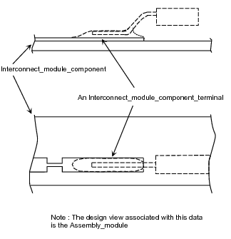
An Interconnect_module_component_terminal is a type of
Physical_component_terminal.
A member of Interconnect_module_component_terminal may be referenced by a member of
Assembly_joint
to describe the partial or complete implementation of a connection defined as a requirement by a member of
Physical_connectivity_definition.
EXAMPLE
Figure 3 illustrates the relationship between an Interconnect_module_component_terminal and its mating feature in an assembly.
Figure 3 — Interconnect_module_component_terminal in an assembly
EXPRESS specification:
            *)

            ENTITY Interconnect_module_component_terminal

              SUBTYPE OF (Physical_component_terminal);


              SELF\Component_feature.definition : Interconnect_module_terminal;


              SELF\Component_feature.associated_definition : Interconnect_module_component;
WHERE

              WR1: NOT EXISTS(SELF\Shape_element.description);

            END_ENTITY;
(*
Attribute definitions:
definition:
specifies the role of the
Interconnect_module_terminal
for the Interconnect_module_component_terminal.
associated_definition:
specifies the role of the
Interconnect_module_component
for the Interconnect_module_component_terminal.
Formal propositions:
WR1:
The
description
shall not be populated.
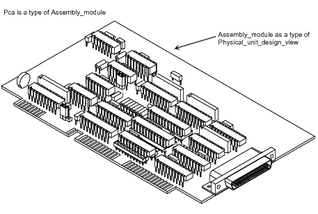
A Layered_assembly_module_design_view is a type of
Assembly_module_design_view.
A Layered_assembly_module_design_view describes a printed circuit assembly.
A printed circuit assembly is nearly a synonym for printed wiring assembly, except that a printed circuit assembly may include
printed components in its printed circuit board and a printed wiring assembly is constructed upon a printed wiring board
that is totally interconnect without printed components.
Another synonym for printed circuit assembly is circuit card assembly.
EXAMPLE
See figure 4 for an illustration of a Layered_assembly_module_design_view.
Figure 4 — Pca
EXPRESS specification:
            *)

            ENTITY Layered_assembly_module_design_view

              SUBTYPE OF (Assembly_module_design_view);


              SELF\Part_design_view.usage_view : Layered_assembly_module_usage_view;

            END_ENTITY;
(*
Attribute definitions:
usage_view:
specifies the
Layered_assembly_module_usage_view,
as seen from the context of its next assembly, for the Layered_assembly_module_design_view.
A Layered_assembly_module_terminal is a type of
Assembly_module_terminal
that is part of the interface between the
Layered_assembly_module_design_view
and its next higher assembly.
EXPRESS specification:
            *)

            ENTITY Layered_assembly_module_terminal

              SUBTYPE OF (Assembly_module_terminal);


              SELF\Part_feature.associated_definition : Layered_assembly_module_usage_view;

            END_ENTITY;
(*
Attribute definitions:
associated_definition:
specifies the role of the
Layered_assembly_module_usage_view
for the Layered_assembly_module_terminal.
A Layered_assembly_module_usage_view is a type of
Assembly_module_usage_view.
A Layered_assembly_module_usage_view provides the information needed to
include the
Layered_assembly_module_design_view
in the design of the next higher level assembly, but not
necessarily sufficient information to reproduce that
Layered_assembly_module_design_view.
NOTE
A
Packaged_connector
may be located in a usage view in addition to terminals.
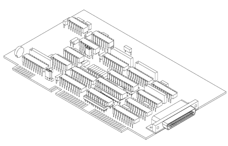
EXAMPLE 1
Figure 2 illustrates details available in a usage view for a
Layered_assembly_module_design_view.
The information available in the usage view specifically is separate from that in the design view and the relationships
between the
two views are usually controlled by a design organization.
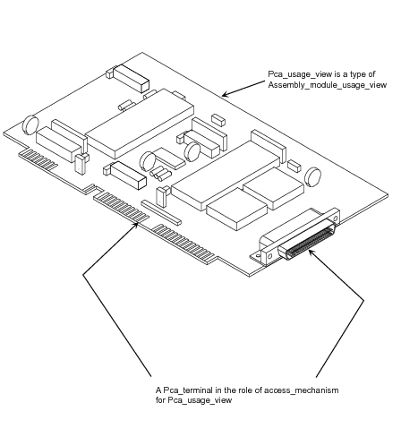
Figure 5 — Layered_assembly_module_usage_view
EXPRESS specification:
            *)

            ENTITY Layered_assembly_module_usage_view

              SUBTYPE OF (Assembly_module_usage_view);


              maximum_negative_component_height :
            OPTIONAL
            Length_data_element;


              maximum_positive_component_height :
            OPTIONAL
            Length_data_element;

            END_ENTITY;
(*
Attribute definitions:
maximum_negative_component_height:
specifies the largest
Length_data_element
in the negative direction from an externally defined datum. The value of this attribute need not be specified.
EXAMPLE 2
An example of the maximum_negative_component_height attribute is for a printed circuit assembly with
through-hole components, where the maximum lead protrusion dimension is given. That dimension is the
maximum_negative_component_height. Another example of the maximum_negative_component_height
attribute is for a printed circuit assembly with surface mounted components on both sides. The
maximum_negative_component_height attribute is for the distance between the established datum and the
maximum material condition of the vertical dimension of the highest surface mount component on the
secondary side of the printed circuit assembly.
maximum_positive_component_height:
specifies the largest
Length_data_element
in the positive direction from an externally defined datum. The value of this attribute need not be specified.
EXAMPLE 3
An example of the maximum_positive_component_height attribute is for a printed circuit assembly where
the maximum component height in the positive direction relative to a datum is given. This dimension
pertains to the fit of the printed circuit assembly in its next assembly. That dimension is the
maximum_positive_component_height.
A Layered_assembly_panel_design_view is a type of
Assembly_module_design_view.
EXPRESS specification:
            *)

            ENTITY Layered_assembly_panel_design_view

              SUBTYPE OF (Assembly_module_design_view);

            END_ENTITY;
(*
A Movable_packaged_component_join_terminal is a type of
Packaged_component_join_terminal.
A Movable_packaged_component_join_terminal is one termination for a
Packaged_component.
The terminal provides access to the electrical functionality of the
packaged_part
being terminated.
EXPRESS specification:
            *)

            ENTITY Movable_packaged_component_join_terminal

              SUBTYPE OF (Packaged_component_join_terminal);


              wire_terminal_length :
            OPTIONAL
            Length_tolerance_characteristic;
WHERE

              WR1: SIZEOF(QUERY(pt <* SELF\Component_feature.definition\Packaged_part_terminal.terminal_of_package |
            NOT('PACKAGE_ARM.WIRE_TERMINAL' IN TYPEOF (pt)))) = 0;

            END_ENTITY;
(*
Attribute definitions:
wire_terminal_length:
specifies the role of the
Length_tolerance_characteristic
for the Movable_packaged_component_join_terminal. The
Length_tolerance_characteristic
need not be provided.
Formal propositions:
WR1:
terminal_of_package
of
Packaged_part_terminal
referred by
definition
inherited from
Packaged_component_join_terminal
shall be a
Wire_terminal.
A Routed_interconnect_component is a type of
Physical_component.
The functionality of a Routed_interconnect_component shall be that of a short.
The domain of the short depends on the material properties of the Routed_interconnect_component.
EXAMPLE
A wire or a jumper or a continuously deposited conductive paste that is included in the design may be represented as a Routed_interconnect_component.
EXPRESS specification:
            *)

            ENTITY Routed_interconnect_component

              SUBTYPE OF (Physical_component);


              routed_centreline_shape : Path_area_with_parameters;
WHERE

              WR1: NOT EXISTS(SELF\Product_view_definition.name);

            END_ENTITY;
(*
Attribute definitions:
routed_centreline_shape:
specifies the role of the
Path_area_with_parameters
for the Routed_interconnect_component.
Formal propositions:
WR1:
The
name
shall not be populated.
A Routed_physical_component is a type of
Physical_component
whose shape is design specific and is routed along a path described by a centreline.
EXAMPLE
A continuously deposited paste that is included in the design may be represented as a Routed_physical_component.
EXPRESS specification:
            *)

            ENTITY Routed_physical_component

              SUBTYPE OF (Physical_component);


              routed_centreline_shape : Path_area_with_parameters;

            END_ENTITY;
(*
Attribute definitions:
routed_centreline_shape:
specifies a role of the
Path_area_with_parameters
for the Routed_physical_component.
This subclause specifies the ARM
subtype constraints for
this module. Each subtype constraint places constraints on the
possible super-type / subtype instantiations.
The ARM subtype constraints and definitions are
specified below.
The
assembly_module_design_view_subtypes
constraint specifies a constraint that applies to instances of
Assembly_module_design_view
and enforces the rule that its subtypes
Layered_assembly_panel_design_view and Layered_assembly_module_design_view
are exclusive.
EXPRESS specification:
            *)
SUBTYPE_CONSTRAINT assembly_module_design_view_subtypes FOR Assembly_module_design_view;

              ONEOF (Layered_assembly_panel_design_view,
         Layered_assembly_module_design_view);

            END_SUBTYPE_CONSTRAINT;
(*
The
physical_component_subtypes
constraint specifies a constraint that applies to instances of
Physical_component
and enforces the rule that its subtypes
Bare_die_component, Packaged_component, Routed_interconnect_component and Routed_physical_component
are exclusive.
EXPRESS specification:
            *)
SUBTYPE_CONSTRAINT physical_component_subtypes FOR Physical_component;

              ONEOF (Bare_die_component,
         Packaged_component,
         Routed_interconnect_component,
         Routed_physical_component);

            END_SUBTYPE_CONSTRAINT;
(*
The
amd_physical_component_terminal_subtypes
constraint specifies a constraint that applies to instances of
Physical_component_terminal
and enforces the rule that its subtypes
Bare_die_component_terminal, Minimally_defined_component_terminal and Packaged_component_join_terminal
are exclusive.
EXPRESS specification:
            *)
SUBTYPE_CONSTRAINT amd_physical_component_terminal_subtypes FOR Physical_component_terminal;

              ONEOF (Bare_die_component_terminal,
         Minimally_defined_component_terminal,
         Packaged_component_join_terminal);

            END_SUBTYPE_CONSTRAINT;
(*
         *)

         END_SCHEMA;  -- Assembly_module_with_interconnect_component_arm
(*
© ISO 2018 — All rights reserved