|
|
Application module:
Package |
ISO/TS 10303-1707:2018-11(E)
© ISO
|
This clause specifies the information requirements for the
Package
application module. The information requirements are specified as the
Application Reference Model (ARM) of this application module.
NOTE 1 A graphical representation of the information
requirements is given in
Annex C.
NOTE 2 The mapping specification is specified in
5.1. It shows how
the information requirements are met by using common resources and
constructs defined or imported in the MIM schema of this application
module.
This clause defines the information requirements to which implementations shall
conform using the EXPRESS language as defined in ISO 10303-11.
The following begins the
Package_arm
schema and identifies the necessary external references.
EXPRESS specification:
         *)

            SCHEMA Package_arm;
(*
The following EXPRESS interface statements specify the elements
imported from the ARMs of other application modules.
EXPRESS specification:
*)

            USE FROM
            Characteristic_arm;
               --
            ISO/TS 10303-1654
            USE FROM
            Geometric_tolerance_arm;
               --
            ISO/TS 10303-1051
            USE FROM
            Non_feature_shape_element_arm;
               --
            ISO/TS 10303-1706
            USE FROM
            Part_feature_function_arm;
               --
            ISO/TS 10303-1712
            REFERENCE FROM
            Support_resource_arm

               --
            ISO/TS 10303-1800
  (bag_to_set);

(*
NOTE 1
The schemas referenced above are specified in the following
part of ISO 10303:
| Characteristic_arm |
ISO/TS 10303-1654 |
| Geometric_tolerance_arm |
ISO/TS 10303-1051 |
| Non_feature_shape_element_arm |
ISO/TS 10303-1706 |
| Part_feature_function_arm |
ISO/TS 10303-1712 |
| Support_resource_arm |
ISO/TS 10303-1800 |
NOTE 2
See Annex C,
Figures
C.1, C.2, C.3and C.4
for a graphical representation of this schema.
This subclause specifies the ARM types
for this application module. The ARM types and
definitions are specified below.
The interface_plane_or_seating_plane type allows for the designation of the data
types
Seating_plane, and Interface_plane.
EXPRESS specification:
            *)

            TYPE
            interface_plane_or_seating_plane =


            SELECT

               (Seating_plane,
    Interface_plane);

            END_TYPE;

            (*
A mounting_technology_type lists the type of the mounting technology.
EXPRESS specification:
            *)

            TYPE
            mounting_technology_type =

            EXTENSIBLE

            ENUMERATION

            OF


            (surface_mount,
    through_hole);

            END_TYPE;

            (*
Enumerated item definitions:
surface_mount:
specifies that component is surface mount;
through_hole:
specifies that component is through hole.
The pa_external_identification_item type is an extension
of the
external_identification_item type.
It adds the data
types
Package_terminal_template_definition, and Package
to the list of alternate data types.
EXPRESS specification:
            *)

            TYPE
            pa_external_identification_item =


            SELECT
            BASED_ON
            external_identification_item
            WITH


               (Package_terminal_template_definition,
    Package);

            END_TYPE;

            (*
The pa_material_item_select type is an extension
of the
material_item_select type.
It adds the data
types
Package_body, and Package_terminal_template_definition
to the list of alternate data types.
EXPRESS specification:
            *)

            TYPE
            pa_material_item_select =


            SELECT
            BASED_ON
            material_item_select
            WITH


               (Package_body,
    Package_terminal_template_definition);

            END_TYPE;

            (*
A predefined_lead_form lists the predefined classification of the lead form provided by this part of
ISO 10303. The form refers to the form as provided by the supplier of the component.
NOTE 1
A externally provided classification scheme may be used to extend the lead form classification over that
provided in this version of this part of ISO 10303.
NOTE 2
An integral terminal form is flush with the body of the package surface.
EXAMPLE
A straight lead that was altered to support orientation requirements would still be classified as a straight
lead since the component manufacturer delived the component with straight leads.
EXPRESS specification:
            *)

            TYPE
            predefined_lead_form =

            EXTENSIBLE

            ENUMERATION

            OF


            (gull_wing,
    j_lead,
    reversed_j_lead,
    integral_terminal,
    undefined,
    ball,
    straight);

            END_TYPE;

            (*
Enumerated item definitions:
gull_wing:
specifies that the predefined form of the lead is gull wing;
j_lead:
specifies that the predefined form of the lead is j lead;
reversed_j_lead:
specifies that the predefined form of the lead is reversed j lead;
integral_terminal:
specifies that the predefined form of the lead is integral terminal;
undefined:
specifies that the predefined form of the lead is undefined;
ball:
specifies that the predefined form of the lead is ball;
straight:
specifies that the predefined form of the lead is straight.
A seating_plane_intersection_type lists the types of the intersection between a feature and
a Seating_plane.
EXPRESS specification:
            *)

            TYPE
            seating_plane_intersection_type =

            ENUMERATION

            OF


            (surface_intersection,
    through_intersection,
    does_not_intersect);

            END_TYPE;

            (*
Enumerated item definitions:
surface_intersection:
specifies that the surface of the feature indicated is congruent with the seating plane;
through_intersection:
specifies that the feature penetrates the seating plane;
does_not_intersect:
specifies that the feature does not intersect the seating plane.
This subclause specifies the ARM entities for this
module. Each ARM application entity is an atomic element that
embodies a unique application concept and contains attributes
specifying the data elements of the entity. The ARM
entities and definitions are specified below.
A Connection_zone_in_part_feature_template_definition is a type of
Connection_zone
in which the context is a Part_feature_template_definition.
A Connection_zone_in_part_feature_template_definition is included in a template definition to provide an explicit geometric model of the
limited areas in the domain of a terminal that are allowed for a valid connection. If the template definition
contains no limitations on the connection area of the terminals associated with the template this Application Object shall
not be provided.
NOTE 1
In some less detailed templates, the entire point domain for features designated as terminals is considered to be available
for connection and the
Connection_zone_in_part_feature_template_definition is redundant.
NOTE 2
In the case where the connection area is necessary, the application shall be carefully reviewed to determine the necessity
for design instances of the connection area as in most cases,
simply using the connection area as a constraint on the allowed location of a joint is sufficient.
NOTE 3
The level of detail included in a template definition may be classified by a user-defined classification system which is
supported by this part of
ISO 10303 but this part of ISO 10303
does not predefine a classification system for template detail level.
EXPRESS specification:
            *)

            ENTITY Connection_zone_in_part_feature_template_definition

              SUBTYPE OF (Connection_zone);


              SELF\Shape_element.associated_definition : Part_feature_template_definition;
WHERE

              WR1: NOT EXISTS(SELF\Shape_element.element_name);

            END_ENTITY;
(*
Attribute definitions:
associated_definition:
specifies the role of the
Part_feature_template_definition
for the Connection_zone_in_part_feature_template_definition.
Formal propositions:
WR1:
The
element_name
shall not be populated.
A Connection_zone_package_interface_plane_relationship is a mechanism
to establish a derived relationship declaration between two connection areas
using a common plane as the interface declaration.
A Connection_zone_package_interface_plane_relationship
may be represented in a geometric context for the purpose of deriving a 2D or 3D
representation.
EXAMPLE
A common application of this is the case where there is a three dimensional model of a terminal where that
terminal is cut by a seating plane and it is necessary to derive a two dimensional area of that terminal for layout purposes.
In this case, the context for both connection areas would be the same terminal definition but
one connection area would be three dimensional and the other connection area would be two
dimensional.
EXPRESS specification:
            *)

            ENTITY Connection_zone_package_interface_plane_relationship;


              interface_plane : interface_plane_or_seating_plane;


              derived_zone : Connection_zone_in_part_feature_template_definition;


              derived_zone_shape_class : STRING;
INVERSE

              associated_package_terminal : SET[0:1] OF Package_terminal_template_definition FOR seating_plane_zone;
WHERE

              WR1: derived_zone_shape_class IN ['area','edge'];

            END_ENTITY;
(*
Attribute definitions:
interface_plane:
specifies the role of the
interface_plane_or_seating_plane
for the Connection_zone_package_interface_plane_relationship.
derived_zone:
specifies the role of the
Connection_zone_in_part_feature_template_definition
for the Connection_zone_package_interface_plane_relationship.
derived_zone_shape_class:
specifies the text that describes the Connection_zone_package_interface_plane_relationship.
associated_package_terminal:
an inverse relationship that specifies that the existence of the Connection_zone_package_interface_plane_relationship
is dependent on the the existence of the
Package_terminal_template_definition
that specifies the Connection_zone_package_interface_plane_relationship as its
seating_plane_zone.
There shall be no more than one
Package_terminal_template_definition
for a Connection_zone_package_interface_plane_relationship.
Formal propositions:
WR1:
The derived_zone_shape_class will be 'area' or 'edge'.
A Guided_wave_terminal is a type of Package_terminal
that is explicitly included for the purpose of providing access to the functionality of a Packaged_part using
guided waves.
EXAMPLE
A Fiber-optic terminal is considered to be a Guided_wave_terminal in this part of ISO 10303
because the signal is launched from the end surface of the terminal.
EXPRESS specification:
            *)

            ENTITY Guided_wave_terminal

              SUBTYPE OF (Package_terminal);

            END_ENTITY;
(*
A Package is a type of a Part_usage_view.
A Package describes a subset of the physical properties of a component relevant to use of that component in an assembly.
Some items are mandatory for any instance of a Package, some items are used for assuring proper orientation and some items
are used for analysis.
A Package includes no more than one package body and one or more package terminals.
A Package includes a seating plane when a mounting technology is specified.
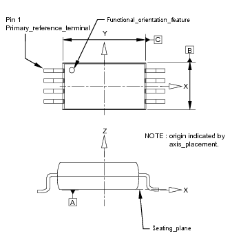
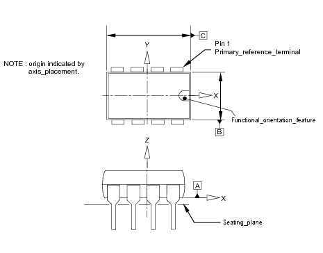
EXAMPLE 1
Figures 1 through 2 illustrate types of Packages and parameters related to Geometric Dimensioning and Tolerancing supported by this part of ISO 10303. ISO 10303-202 would
be used in conjunction with this part of ISO 10303 to define the exchange of the presentation information (i.e., the drawings).
This part of ISO 10303 supports the direct application to application exchange of the parametric data illustrated in the
drawings.
Figure 1 — Axial lead
Figure 2 — T099
EXAMPLE 2
Figures 3 through 4
illustrate parameters and features related to Package orientation for assembly purposes supported by this part of ISO 10303.
ISO 10303-202 would be used in conjunction with this part of ISO 10303 to define the exchange of the presentation information
(i.e., the drawings).
Figure 3 — Twenty pin orientation features
Figure 4 —
and for discrete devices
NOTE 1
The location of the Primary_reference_terminal as illustrated
in Figure 4 is not constrained by electrical functionality
unless there are visually identifiable features that indicate polarity or orientation requirements. The top row in the Figure
illustrates three situations where there are no visual features indicating requirements
and the selection is arbitrary. The polarized part in the second row in the
Figure illustrates a case where there is a visual feature indicating a functional orientation requirement due to the nature
of the part.
NOTE 2
When used for a Packaged_part "white box model",
the Part_device
is installed in the Package and an electrical connection is defined between each terminal on the installed
Part_device and one or more terminals on the Package.
EXPRESS specification:
            *)

            ENTITY Package

              SUBTYPE OF (Part_usage_view);


              mounting_technology :
            OPTIONAL
            mounting_technology_type;


              maximum_seating_plane_installation_offset :
            OPTIONAL
            Length_data_element;


              nominal_mounting_lead_pitch :
            OPTIONAL
            Length_data_element;


              nominal_mounting_lead_span :
            OPTIONAL
            Length_data_element;


              maximum_body_height_above_seating_plane :
            OPTIONAL
            Length_data_element;


              maximum_body_height_below_seating_plane :
            OPTIONAL
            Length_data_element;


              body_clearance_above_seating_plane :
            OPTIONAL
            Length_tolerance_characteristic;


              body_clearance_below_seating_plane :
            OPTIONAL
            Length_tolerance_characteristic;


              maximum_lead_length_below_seating_plane :
            OPTIONAL
            Length_data_element;


              least_lead_length_below_seating_plane :
            OPTIONAL
            Length_data_element;
DERIVE

              maximum_package_total_vertical_extent : Length_data_element := max_data_element(
            											add_data_element(maximum_body_height_above_seating_plane,maximum_body_height_below_seating_plane),
            											    add_data_element(maximum_body_height_above_seating_plane,maximum_lead_length_below_seating_plane));

              cutout_required : LOGICAL := (maximum_body_height_below_seating_plane\Value_with_unit.value_component > 0.0);

              maximum_installed_height : Length_data_element := add_data_element(maximum_body_height_above_seating_plane,maximum_seating_plane_installation_offset);

              one_orientation_feature : LOGICAL := (SIZEOF(orientation_feature) = 1);

              two_orientation_features : LOGICAL := (SIZEOF(orientation_feature) = 2);

              three_orientation_features : LOGICAL := (SIZEOF(orientation_feature) = 3);

              package_seating_plane : SET[0:?] OF Seating_plane := bag_to_set(QUERY(nfse <* USEDIN(SELF, 'NON_FEATURE_SHAPE_ELEMENT_ARM.NON_FEATURE_SHAPE_ELEMENT.ASSOCIATED_DEFINITION')|
            'NON_FEATURE_SHAPE_ELEMENT_ARM.SEATING_PLANE' IN TYPEOF(nfse)));

              interface_plane : SET[0:?] OF Interface_plane := bag_to_set(QUERY(nfse <* USEDIN(SELF, 'NON_FEATURE_SHAPE_ELEMENT_ARM.NON_FEATURE_SHAPE_ELEMENT.ASSOCIATED_DEFINITION')|
            'NON_FEATURE_SHAPE_ELEMENT_ARM.INTERFACE_PLANE' IN TYPEOF(nfse)));
INVERSE

              body : SET[0:1] OF Package_body FOR associated_definition;

              package_accesses : SET[0:?] OF Package_terminal FOR associated_definition;

              package_polarity_indication : SET[0:1] OF Polarity_indication_feature FOR associated_definition;

              orientation_feature : SET[0:3] OF Package_orientation_feature FOR associated_definition;
WHERE

              WR1: NOT (mounting_technology = surface_mount) OR (NOT (EXISTS(maximum_lead_length_below_seating_plane) OR EXISTS(least_lead_length_below_seating_plane)));

              WR2: NOT (EXISTS(maximum_lead_length_below_seating_plane)) OR (maximum_lead_length_below_seating_plane\Value_with_unit.value_component
            > 0.0);

              WR3: NOT (EXISTS(least_lead_length_below_seating_plane)) OR (least_lead_length_below_seating_plane\Value_with_unit.value_component
            > 0.0);

              WR4: NOT EXISTS(mounting_technology) OR (SIZEOF(package_seating_plane) = 1);

              WR5: SIZEOF(QUERY(pa <* package_accesses | 'PACKAGE_ARM.PRIMARY_REFERENCE_TERMINAL' IN TYPEOF(pa))) = 1;

              WR6: SIZEOF(QUERY(nt <* package_accesses |
            	                      EXISTS(nt\Part_feature.precedent_feature)
            	               )) = (SIZEOF(package_accesses) - 1);

              WR7: SIZEOF(QUERY(nt <* package_accesses |
            	                     (SIZEOF(nt\Part_feature.subsequent_feature) = 1)
            	               )) = (SIZEOF(package_accesses) - 1);

              WR8: NOT one_orientation_feature    OR ('PACKAGE_ARM.PRIMARY_ORIENTATION_FEATURE' IN TYPEOF(orientation_feature[1]));

              WR9: NOT two_orientation_features   OR ((SIZEOF(QUERY(orf <* orientation_feature |
            ('PACKAGE_ARM.PRIMARY_ORIENTATION_FEATURE' IN TYPEOF(orf)))) = 1) AND
            (SIZEOF(QUERY(orf <* orientation_feature |
            ('PACKAGE_ARM.SECONDARY_ORIENTATION_FEATURE' IN TYPEOF(orf)))) = 1));

              WR10: NOT three_orientation_features OR ((SIZEOF(QUERY(orf <* orientation_feature |
            ('PACKAGE_ARM.PRIMARY_ORIENTATION_FEATURE' IN TYPEOF(orf)))) = 1) AND
            (SIZEOF(QUERY(orf <* orientation_feature |
            ('PACKAGE_ARM.SECONDARY_ORIENTATION_FEATURE' IN TYPEOF(orf)))) = 1) AND
            (SIZEOF(QUERY(orf <* orientation_feature |
            ('PACKAGE_ARM.TERTIARY_ORIENTATION_FEATURE' IN TYPEOF(orf)))) = 1));

            END_ENTITY;
(*
Attribute definitions:
mounting_technology:
specifies a value of mounting_technology_type for the Package. The Surface_mount indicates that the Package_terminals have a Connection_zone that is congruent with the package_seating_plane and through_hole indicates the terminals penetrate the package_seating_plane. The value of this attribute need not be specified.
maximum_seating_plane_installation_offset:
specifies the maximum offset of the seating plane installation of the Package. The value of this attribute need not be specified.
nominal_mounting_lead_pitch:
specifies the nominal mounting pitch of the Package. The value of this attribute need not be specified.
nominal_mounting_lead_span:
specifies the nominal mounting span of the Package. The value of this attribute need not be specified.
maximum_body_height_above_seating_plane:
specifies the maximum
height of the Package above the seating plane. Since there is no attribute describing the maximum terminal height above the seating plane, this
attribute shall be interpreted as the furthest point away from the seating plane of either the body or of any Package_terminal above the seating plane. The value of this attribute need not be specified.
EXAMPLE 3
In the case of package to be mounted in a cutout, there may only be the surface mounted leads protruding above the seating
plane.
maximum_body_height_below_seating_plane:
specifies the maximum height of the Package below the seating plane. The value of this attribute need not be specified.
body_clearance_above_seating_plane:
specifies a Length_tolerance_characteristic that is the minimum length between the body and the Seating_plane. The value of this attribute need not be specified.
body_clearance_below_seating_plane:
specifies a Length_tolerance_characteristic that is the minimum length between the body and the Seating_plane. The value of this attribute need not be specified.
maximum_lead_length_below_seating_plane:
specifies the maximum lead length below the seating plane. The value of this attribute need not be specified.
least_lead_length_below_seating_plane:
specifies the smallest lead length
below the seating plane. The value of this attribute need not be specified.
maximum_package_total_vertical_extent:
specifies maximum package vertical extent that is a maximum of sum of maximum_body_height_above_seating_plane and maximum_body_height_below_seating_plane,
and sum of maximum_body_height_above_seating_plane and maximum_lead_length_below_seating_plane.
cutout_required:
specifies a derived value of TRUE or FALSE, depending on the existence of the optional attribute maximum_body_height_below_seating_plane. If the attribute exists, the value is TRUE. If the attribute is no present, the value is FALSE.
maximum_installed_height:
specifies the sum of maximum_body_height_above_seating_plane and maximum_seating_plane_installation_offset.
one_orientation_feature:
the attribute is TRUE only if the size of orientation_feature is one.
two_orientation_features:
the attribute is TRUE only if the size of orientation_feature is two.
three_orientation_features:
the attribute is TRUE only if the size of orientation_feature is three.
package_seating_plane:
specifies the role of the
Seating_plane
for the Package.
The
Seating_plane
simulates the mounting surface for the terminals in the case of surface mounted parts and in the case of through-hole technology,
an arbitrarily established mounting surface. Terminals are required to approach the
Seating_plane
from the top, which is the side where the values on the Z axis are positive.
Package installation is defined to be only from the top of the
Seating_plane
in order to reduce orientation errors between two-dimensional and three-dimensional models in this part of ISO 10303.
interface_plane:
specifies the role of the
Interface_plane
for the Package.
The Interface_plane
simulates the interface surface of an external device. There shall exist zero or more
Interface_planes
in the role of interface_plane.
NOTE 3
The interface_plane is typically used for connectors, but may be used for modules.
EXAMPLE 4
A use of interface_plane is in the case of a fiber-optic transceiver that is mounted on a PCB but has a right angle connector to interface with a
fiber.
body:
specifies an inverse relationship that specifies that the existence of the Package
is dependent on the existence of the
Package_body
that specifies the Package
as its
associated_definition.
There shall be no more than one
Package_body
for a particular Package.
package_accesses:
an inverse relationship that specifies that the existence of the Package is dependent on the existence of the
Package_terminal
that specifies the Package as its
associated_definition.
There shall be zero or more
Package_terminal
for a Package.
package_polarity_indication:
specifies an inverse relationship that specifies that the existence of the Package
is dependent on the existence of the
Polarity_indication_feature
that specifies the Package
as its
associated_definition.
There shall be no more than one
Polarity_indication_feature
for a Package in this role.
orientation_feature:
specifies an inverse relationship that specifies that the existence of the Package
is dependent on the existence of the
Package_orientation_feature
that specifies the Package
as its
associated_definition.
There shall be no more than three
Package_orientation_features
for a particular Package.
Formal propositions:
WR1:
If mounting_technology is surface_mount, then
maximum_lead_length_below_seating_plane and least_lead_length_below_seating_plane shall not be provided.
WR2:
If maximum_lead_length_below_seating_plane is provided, then value_component
of maximum_lead_length_below_seating_plane shall be greater than zero.
WR3:
If least_lead_length_below_seating_plane is provided, then value_component
of least_lead_length_below_seating_plane shall be greater than zero.
WR4:
If mounting_technology is supplied, then the size of package_seating_plane shall be one.
WR5:
The Product refered by
of_product of
defined_version shall
be assigned by Product_category_assignment
to at least one Product_category with
name 'package'.
WR6:
There shall be one Primary_reference_terminal in package_accesses.
WR7:
Each member of package_accesses except for one shall specify a
precedent_feature.
NOTE 4
Only the
Primary_reference_terminal
shall not specify a precedent_feature.
WR8:
Each member of package_accesses except for one shall specify a
subsequent_feature.
NOTE 5
Constraints WR6, WR7 and WR8 exist to support user-defined ordering because this part of ISO 10303 does not predefine an
order on the terminals.
Data that satisfies the constraints will have the properties of a list with unique entries; the list may have missing entries.
EXAMPLE 5
A BGA definition includes a set of relationships that declare that the terminal labeled "AB1" is earlier in the numbering
sequence than "BC2".
Some of the grid intersections do not have terminals so the grid has voids.
EXAMPLE 6
A six pin SIP definition has terminals labeled "1" through "6" inclusively.
WR9:
If there is one orientation_feature then it shall be a
Primary_orientation_feature.
WR10:
If there are two orientation_features then one of them shall be a
Primary_orientation_feature
and the other shall be a
Secondary_orientation_feature.
A Package_body is a type of
Part_feature
that is the
encasement used in the realization of a Package. The observer view shall be above the seating plane and
shall be higher than the highest point of the Package_body.
EXPRESS specification:
            *)

            ENTITY Package_body

              SUBTYPE OF (Part_feature);


              SELF\Part_feature.associated_definition : Package;
INVERSE

              body_material : Material_identification FOR items;
WHERE

              WR1: SIZEOF(QUERY(pf <* USEDIN(SELF,
            'PACKAGE_ARM.PACKAGE_BODY_SURFACE.ASSOCIATED_PACKAGE_BODY') | ('PACKAGE_ARM.' + 'PACKAGE_BODY_TOP_SURFACE' IN TYPEOF(pf))))
            <= 1;

              WR2: SIZEOF(QUERY(pf <* USEDIN(SELF,
            'PACKAGE_ARM.PACKAGE_BODY_SURFACE.ASSOCIATED_PACKAGE_BODY') | ('PACKAGE_ARM.' + 'PACKAGE_BODY_BOTTOM_SURFACE' IN TYPEOF(pf))))
            <= 1;

              WR3: SIZEOF(QUERY(pf <* USEDIN(SELF,
            'PACKAGE_ARM.PACKAGE_BODY_SURFACE.ASSOCIATED_PACKAGE_BODY') | ('PACKAGE_ARM.' + 'PACKAGE_BODY_EDGE_SURFACE' IN TYPEOF(pf))))
            <= 1;

              WR4: 'CONDUCTIVITY_MATERIAL_ASPECTS_ARM.'+ 'MATERIAL_IDENTIFICATION_WITH_CONDUCTIVITY_CLASSIFICATION' IN TYPEOF (body_material);

            END_ENTITY;
(*
Attribute definitions:
associated_definition:
an inherited attribute shall be of type
Package
for the Package_body.
body_material:
specifies an inverse relationship that specifies that the existence of the Package_body
is dependent on the existence of the
Material_identification
that specifies the Package_body
as its
items.
Formal propositions:
WR1:
There shall be no more than one Package_body_top_surface
refering Package_body as associated_definition.
WR2:
There shall be no more than one Package_body_bottom_surface
refering Package_body as associated_definition.
WR3:
There shall be no more than one Package_body_edge_surface
refering Package_body as associated_definition.
WR4:
The body_material shall be the Material_identification_with_conductivity_classification.
A Package_body_bottom_surface is a type of Package_body_surface that is not visible from an observer located
so as to place the component on a substrate. The Package_body_bottom_surface is visible from the seating plane associated with the Package.
NOTE
In typical cases the Package_body_bottom_surface is the surface of the package body closest to
the seating plane.
EXPRESS specification:
            *)

            ENTITY Package_body_bottom_surface

              SUBTYPE OF (Package_body_surface);

            END_ENTITY;
(*
A Package_body_edge_segment_surface is a type of
Package_body_surface.
A Package_body_edge_segment_surface is a segment along the edge of the body between the top and bottom
surfaces.
EXAMPLE
A BGA package may have four or five edge segments depending on whether the location of pin A2 is indicated
by a chamfered corner.
EXPRESS specification:
            *)

            ENTITY Package_body_edge_segment_surface

              SUBTYPE OF (Package_body_surface);


              composed_surface : Package_body_edge_surface;


              start_vertex : Edge_segment_vertex;


              end_vertex : Edge_segment_vertex;
WHERE

              WR1: start_vertex :<>: end_vertex;

            END_ENTITY;
(*
Attribute definitions:
composed_surface:
specifies the Package_body_edge_surface for the Package_body_edge_segment_surface.
start_vertex:
specifies the
Edge_segment_vertex
for the Package_body_edge_segment_surface.
end_vertex:
specifies the
Edge_segment_vertex
for the Package_body_edge_segment_surface.
Formal propositions:
WR1:
The start_vertex shall not be the end_vertex.
A Package_body_edge_surface is a type of
Package_body_surface.
A Package_body_edge_surface is the surface between the top and bottom surfaces.
NOTE
The structural model of a package provided in this part of ISO 10303 is not intended to be exhaustive
but to provide for coverage of typical needs in physical design, including spacing checks. It is
anticipated that if complex shapes are desired, then the three dimensional geometric modeling support
provided will be used.
EXAMPLE
A usual case for a structural model of a TO-99 case in two dimensions would be that the cross-section of
maximum extent would be used to derive the edge segments, because that cross-section is where the
orientation tab is located.
EXPRESS specification:
            *)

            ENTITY Package_body_edge_surface

              SUBTYPE OF (Package_body_surface);

            END_ENTITY;
(*
A Package_body_surface is a type of Part_feature.
A Package_body_surface is one of a
Package_body_bottom_surface,
a Package_body_top_surface,
a Package_body_edge_segment_surface, or
a Package_body_edge_surface.
A Package_body_surface relationship to the seating plane may be explicitly established.
If an explicit relationship is not established the interpretation shall be that the bottom surface
is adjacent to or congruent with the seating plane.
EXPRESS specification:
            *)

            ENTITY Package_body_surface

              ABSTRACT SUPERTYPE

            OF (ONEOF (Package_body_bottom_surface,
                                Package_body_top_surface,
                                Package_body_edge_segment_surface,
                                Package_body_edge_surface))

              SUBTYPE OF (Part_feature);


              associated_package_body : Package_body;

            END_ENTITY;
(*
Attribute definitions:
associated_package_body:
specifies the role of the Package_body for the Package_body_surface.
A Package_body_top_surface is a type of Package_body_surface that is visible from any observer located so as
to place the component on a substrate.
NOTE
In typical cases in a three dimensional model, the normal vector of the geometric item representing the
Package_body_top_surface
is parallel with the normal vector of the geometric item representing the seating plane.
EXPRESS specification:
            *)

            ENTITY Package_body_top_surface

              SUBTYPE OF (Package_body_surface);

            END_ENTITY;
(*
A Package_orientation_feature is a type of
Part_feature. This
permits the explicit creation of reference frames in order to support unambiguous orientation independent
of differences between model coordinate systems because the datum reference frames are based on model
geometry and not arbitrary coordinate systems.
This supports easier exchange and conversion of model libraries because the mapping is not dependent on discovery of
coordinate system orientation differences.
A Package_orientation_feature participates in providing for the unambiguous orientation of a part in its next assembly.
A Package_orientation_feature is either a
Primary_orientation_feature
or a
Secondary_orientation_feature
or a
Tertiary_orientation_feature.
EXPRESS specification:
            *)

            ENTITY Package_orientation_feature

              ABSTRACT SUPERTYPE

            OF (ONEOF (Primary_orientation_feature,
                                Secondary_orientation_feature,
                                Tertiary_orientation_feature))

              SUBTYPE OF (Part_feature);


              associated_body_vertical_extent :
            OPTIONAL
            SET[1:2] OF Package_body_surface;


              SELF\Part_feature.associated_definition : Package;
WHERE

              WR1: 'GEOMETRIC_TOLERANCE_ARM.DATUM_FEATURE' IN TYPEOF(SELF);

            END_ENTITY;
(*
Attribute definitions:
associated_body_vertical_extent:
specifies the role of
the Package_body_surface
for the Package_orientation_feature. There shall exist one or two
Package_body_surfaces
for a Package_orientation_feature. The value of this attribute need not be specified.
associated_definition:
an inherited attribute shall be of type
Package
for the Package_orientation_feature.
Formal propositions:
WR1:
A Package_orientation_feature shall define a
Datum_feature.
A Package_terminal is a type of
Part_feature and a type of Placed_feature.
When the case or package body is used as a terminal, then Package_terminal shall be populated to specify the feature of the
Package_body that serves that purpose.
The Package_terminal shall be in a sequence, with the initial member being
Primary_reference_terminal, and each member that is not a
Primary_reference_terminal shall reference the previous member in the sequence
using the precedent_feature
attribute inherited from Part_feature.
The external_connection_zone shall be populated.
When the connection area inherited from the supertype of this Application Object is populated, the interpretation shall be
that the inherited connection area overrides the
external_connection_zone.
NOTE
The feature_shape
specified by the terminal or mounting feature may be the same feature_shape that is specified by the associated
Connection_zone. In this case the whole
terminal is the Connection_zone.
EXPRESS specification:
            *)

            ENTITY Package_terminal

              SUBTYPE OF (Part_feature, Placed_feature);


              SELF\Placed_feature.definition : Package_terminal_template_definition;


              SELF\Part_feature.associated_definition : Package;
INVERSE

              feature_shape : SET[1:?] OF Usage_concept_usage_relationship FOR associated_usage;

            END_ENTITY;
(*
Attribute definitions:
definition:
an inherited attribute shall be of type
Package_terminal_template_definition
for the Package_terminal.
associated_definition:
an inherited attribute shall be of type
Package
for the Package_terminal.
feature_shape:
specifies an inverse relationship that specifies that the existence of the Package_terminal
is dependent on the existence of the
Usage_concept_usage_relationship
that specifies the Package_terminal
as its
associated_usage.
There shall be one or more
Usage_concept_usage_relationships
for a particular Package_terminal.
A Package_terminal_surface_constituent_relationship is a type of
Shape_element_relationship.
It associates the surface of the package to a terminal via Shape_element.
EXPRESS specification:
            *)

            ENTITY Package_terminal_surface_constituent_relationship

              SUBTYPE OF (Shape_element_relationship);


              SELF\Shape_element_relationship.relating : Package_body_surface;


              SELF\Shape_element_relationship.related : Package_terminal;

            END_ENTITY;
(*
Attribute definitions:
relating:
an inherited attribute shall be of type
Package_body_surface
for the Package_terminal_surface_constituent_relationship.
related:
an inherited attribute shall be of type
Package_terminal
for the Package_terminal_surface_constituent_relationship.
A Package_terminal_template_definition is a type of
Part_feature_template_definition.
The seating_plane_zone shall not exist if the seating_plane_intersection attribute is 'does not intersect'.
The seating_plane_intersection attribute shall not be 'does not intersect' if the seating_plane_zone
attribute exists.
NOTE 1
The
Seating_plane
referenced indirectly by this terminal may be in the role of
interface_plane
for the
Package
referenced by
associated_definition.
EXAMPLE
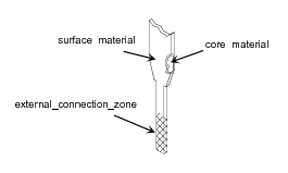
Figure 5 illustrates a cutaway view of a terminal template definition and shows
the characteristics related to the definition.
Figure 5 — Package_terminal_template_definition characteristics
EXPRESS specification:
            *)

            ENTITY Package_terminal_template_definition

              SUBTYPE OF (Part_feature_template_definition);


              SELF\Feature_definition_with_connection_area.connection_area RENAMED external_connection_zone :
            OPTIONAL
            SET[1:?] OF Connection_zone_in_part_feature_template_definition;


              internal_connection_zone :
            OPTIONAL
            SET[1:?] OF Connection_zone_in_part_feature_template_definition;


              lead_form :
            OPTIONAL
            predefined_lead_form;


              seating_plane_intersection :
            OPTIONAL
            seating_plane_intersection_type;


              terminal_characteristic :
            OPTIONAL
            SET[1:?] OF characteristic;


              terminal_diametrical_extent :
            OPTIONAL
            Length_tolerance_characteristic;


              seating_plane_zone :
            OPTIONAL
            Connection_zone_package_interface_plane_relationship;
DERIVE

              mates_with_substrate : BOOLEAN := (EXISTS(seating_plane_zone));

              terminal_core_material : SET[0:1] OF Material_identification := bag_to_set(QUERY( temp <* USEDIN(SELF,
            'GENERIC_MATERIAL_ASPECTS_ARM.MATERIAL_IDENTIFICATION.ITEMS') |
            (SIZEOF( QUERY( cla <* USEDIN(temp,'CLASSIFICATION_ASSIGNMENT_ARM.' +
            	'CLASSIFICATION_ASSIGNMENT.' + 'ITEMS') | cla.role = 'terminal core material')) = 1)));

              terminal_surface_material : SET[0:1] OF Material_identification := bag_to_set(QUERY( temp <* USEDIN(SELF,
            'GENERIC_MATERIAL_ASPECTS_ARM.MATERIAL_IDENTIFICATION.ITEMS') |
            (SIZEOF( QUERY( cla <* USEDIN(temp,'CLASSIFICATION_ASSIGNMENT_ARM.' +
            	'CLASSIFICATION_ASSIGNMENT.' + 'ITEMS') | cla.role = 'terminal surface material')) = 1)));
INVERSE

              external_lead_form : SET[0:1] OF External_source_identification FOR item;
WHERE

              WR1: NOT EXISTS(seating_plane_zone) OR (SIZEOF(QUERY(cz <* external_connection_zone | (seating_plane_zone.derived_zone = cz)))
            = 1);

              WR2: NOT EXISTS(seating_plane_zone) OR ((seating_plane_intersection = surface_intersection) OR (seating_plane_intersection
            = through_intersection));

              WR3: NOT ((seating_plane_intersection = does_not_intersect) AND (EXISTS(seating_plane_zone)));

              WR4: NOT (SIZEOF(terminal_core_material) = 1) OR
            ('CONDUCTIVITY_MATERIAL_ASPECTS_ARM.MATERIAL_IDENTIFICATION_WITH_CONDUCTIVITY_CLASSIFICATION' IN TYPEOF (terminal_core_material[1]));

              WR5: (SIZEOF(terminal_surface_material) = 1) AND
            ('CONDUCTIVITY_MATERIAL_ASPECTS_ARM.MATERIAL_IDENTIFICATION_WITH_CONDUCTIVITY_CLASSIFICATION' IN TYPEOF (terminal_surface_material[1]));

              WR6: (EXISTS (lead_form)) XOR ((SIZEOF(external_lead_form)) = 1);

            END_ENTITY;
(*
Attribute definitions:
external_connection_zone:
specifies the
Connection_zone_in_part_feature_template_definition
on the outside surface of the Package_terminal_template_definition. There may be more than one
Connection_zone_in_part_feature_template_definition
for a Package_terminal_template_definition.
The value of this attribute need not be specified. If the source system contains the data, then the
external_connection_zone shall be supplied.
internal_connection_zone:
specifies the
Connection_zone_in_part_feature_template_definition
on the inside portion of the Package_terminal_template_definition. There may be more than one
Connection_zone_in_part_feature_template_definition
in the role of
internal_connection_zone. The value of this attribute need not be specified.
lead_form:
specifies the
predefined_lead_form
for the Package_terminal_template_definition. The value of this attribute need not be specified.
seating_plane_intersection:
specifies whether or not the shape of the Package_terminal_template_definition intersects the shape of the seating plane to within the
tolerance of the geometric context. The values allowed for the attribute are
'surface_intersection',
'through_intersection',
'does_not_intersect'.
NOTE 2
Not all terminals need to intersect the seating plane.
terminal_characteristic:
specifies the role of the
characteristic
for the Package_terminal_template_definition. There shall exist one or more
characteristics
for the Package_terminal_template_definition.
The value of this attribute need not be specified.
terminal_diametrical_extent:
specifies the Length_tolerance_characteristic that
represents the diameter of a Package_terminal_template_definition.
The Length_tolerance_characteristic is the diameter of
a circle that circumscribes the cross-sectional shape of the terminal.
seating_plane_zone:
specifies the role of the Connection_zone_package_interface_plane_relationship
for the Package_terminal_template_definition. The value of this attribute need not be specified.
mates_with_substrate:
an attribute's value becomes TRUE only then seating_plane_zone exists and it's
interface_plane
is package_seating_plane of
associated_definition.
terminal_core_material:
specifies the role of the
Material_identification for the
Package_terminal_template_definition core material. The value of this attribute need not be specified.
terminal_surface_material:
specifies the role of the
Material_identification for the outer surface
of the Package_terminal_template_definition surface
material.
external_lead_form:
an inverse relationship that specifies that the existence of the Package_terminal_template_definition is dependent on the existence of the
External_source_identification
that specifies the Package_terminal_template_definition as its
item.
There shall exist not more than one
External_source_identification
for a Package_terminal_template_definition.
Formal propositions:
WR1:
If seating_plane_zone is provided, then it's
derived_zone
shall be in external_connection_zone.
WR2:
If seating_plane_zone is provided, then seating_plane_intersection shall be
surface_intersection
or through_intersection.
WR3:
If seating_plane_zone is provided, then seating_plane_intersection shall not be
does_not_intersect.
WR4:
If terminal_core_material is provided, it shall be the
Material_identification_with_conductivity_classification.
WR5:
The terminal_surface_material shall be the
Material_identification_with_conductivity_classification.
WR6:
The lead_form or the external_lead_form shall be provided but not both.
A Polarity_indication_feature is a type of
Part_feature. A Polarity_indication_feature provides visible or tactile means to reduce or eliminate ambiguity of the location of a polarized part in an assembly operation.
A Polarity_indication_feature shall not be used to identify orientation features of non-polarized components.
NOTE
Other orientation information may be required in addition to the Polarity_indication_feature to totally disambiguate the correct orientation.
EXPRESS specification:
            *)

            ENTITY Polarity_indication_feature

              SUBTYPE OF (Part_feature);


              associated_body_vertical_extent :
            OPTIONAL
            SET[1:2] OF Package_body_surface;


              associated_terminal : Package_terminal;


              SELF\Part_feature.associated_definition : Package;

            END_ENTITY;
(*
Attribute definitions:
associated_body_vertical_extent:
specifies a set of Package_body_surface for the polarity indication feature. There may be one or two Package_body_surface for the Polarity_indication_feature. The value of this attribute need not be specified.
associated_terminal:
specifies the Package_terminal for the polarity indication feature.
associated_definition:
an inherited attribute shall be of type
Package
for the Polarity_indication_feature.
A Primary_orientation_feature is a type of
Package_orientation_feature.
A Primary_orientation_feature is the first
orientation feature
in the sequence of
one to three orientation features
associated with the Package.
NOTE
A Primary_orientation_feature is not usually also a Primary_reference_terminal.
EXAMPLE 1
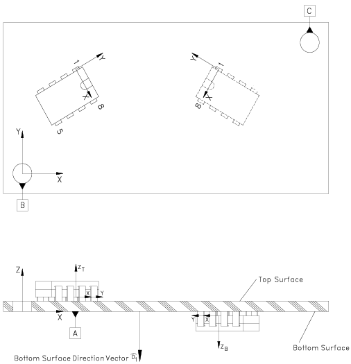
Figure 6 illustrates two of the three-dimensional geometric relationships between a component and the printed circuit board it is
mounted on. A datum system is included for reference purposes. The Z direction is parallel to the normal of the top surface
of the board. Both the top and bottom surface normal vectors are parallel to the normal vectors of the seating plane for
the components.
Figure 6 — Three-dimensional assembly relationships
EXAMPLE 2
Figure 7 illustrates two of the two-dimensional geometric relationships between a component and the printed circuit board it is mounted
on. A datum system is included for reference purposes.
Figure 7 — Two-dimensional assembly relationships
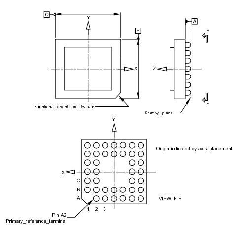
EXAMPLE 3
Figures 8 through
9 illustrates orientation details for
microcircuit packages. In Figures 8 and
9 the bottom surface of
the package is the Primary_orientation_feature.
The assignment of Datum A indicates this fact.
Figure 8 — Twenty pin orientation features
Figure 9 — Ball grid array orientation features
EXAMPLE 4
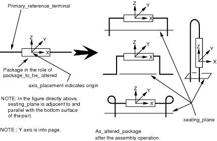
Figure 10
illustrates details associated with several variations of an Axial package modification and the associated
Seating_plane.
In each case , the seating plane orientation with respect to the
Axis_placement is constant,
while the Package shape orientation changes
due to the modification.
Figure 10 — Axial modifications and resulting orientations
EXAMPLE 5
Figure 11 illustrates Primary_reference_terminal assignment and also assignment of Polarity_indication_feature. Knowledge of Polarity_indication_features separate from the orientation feature increases the ability to determine when to use polarity indication symbols on the interconnect
substrate for polarized components e.g., polarized capacitors, diodes).
Figure 11 — and for discrete devices
Figure 12 — Eight lead gull wing orientation features
Figure 13 — Eight lead DIP orientation features
Figure 14 — TO-99 orientation features
EXPRESS specification:
            *)

            ENTITY Primary_orientation_feature

              SUBTYPE OF (Package_orientation_feature);

            END_ENTITY;
(*
A Primary_reference_terminal is a type of Package_terminal.
This terminal is assigned the identifier string that is first in the
sequence of package terminal names to be assigned to the part. The Primary_reference_terminal
shall not specify a precedent_feature and is the first member of the sequence of Package_terminal.
The sort order of the names assigned to the Packaged_terminals is defined
by the explicit sequence established by the use of precedent_feature inherited from Part_feature.
EXAMPLE
If a value of '1' is available, assigning a value of '2' to this terminal
would be prohibited by this part of ISO 10303, due to the possibility of confusion.
NOTE
The Primary_reference_terminal is often associated with an orientation
feature, but it may not be the orientation feature itself. Usually the
Primary_reference_terminal and the
Primary_orientation_feature are
different part_features.
EXPRESS specification:
            *)

            ENTITY Primary_reference_terminal

              SUBTYPE OF (Package_terminal);
WHERE

              WR1: NOT (EXISTS(SELF\Part_feature.precedent_feature));

            END_ENTITY;
(*
Formal propositions:
WR1:
The
precedent_feature
shall not be populated.
A Secondary_orientation_feature is a type of
Package_orientation_feature.
A Secondary_orientation_feature provides anti-rotation capability for unambiguous orientation of the part in the datum reference frame.
A Secondary_orientation_feature is the second
orientation feature in the sequence of
one to three orientation features
associated with the Package.
If a Secondary_orientation_feature
is populated for a Package
, then a member of
Primary_orientation_feature
shall be populated for that Package.
EXPRESS specification:
            *)

            ENTITY Secondary_orientation_feature

              SUBTYPE OF (Package_orientation_feature);

            END_ENTITY;
(*
A Tertiary_orientation_feature is a type of
Package_orientation_feature.
A Tertiary_orientation_feature provides anti-rotation capability for unambiguous orientation of the part in the datum reference frame.
A Tertiary_orientation_feature is the third
orientation feature
in the sequence of
one to three orientation features
associated with the Package. If a Tertiary_orientation_feature
is populated for a Package, then a member of
Secondary_orientation_feature
and a member of
Primary_orientation_feature
shall be populated for that Package.
EXPRESS specification:
            *)

            ENTITY Tertiary_orientation_feature

              SUBTYPE OF (Package_orientation_feature);

            END_ENTITY;
(*
A Visual_orientation_feature is a type of
Part_feature.
A Visual_orientation_feature provides visible or tactile means to reduce or eliminate ambiguity of the location of a
Primary_reference_terminal
in an assembly operation.
NOTE
Other orientation information may be required in addition to the Visual_orientation_feature to totally disambiguate the correct
orientation.
EXAMPLE
A mark on a component implemented with ink or a visible indentation or a formed corner may be used to indicate the fact that
pin one
of the package is in close proximity to the mark. A vision system or a human operator will use the mark to correctly orient
the
component.
EXPRESS specification:
            *)

            ENTITY Visual_orientation_feature

              SUBTYPE OF (Part_feature);


              associated_body_vertical_extent :
            OPTIONAL
            SET[1:2] OF Package_body_surface;


              associated_terminal : Package_terminal;

            END_ENTITY;
(*
Attribute definitions:
associated_body_vertical_extent:
specifies the
Package_body_surface
for the Visual_orientation_feature.
There shall be one or two
package_body_surfaces
for a Visual_orientation_feature.
The value of this attribute need not be specified.
associated_terminal:
specifies the
Package_terminal
for the Visual_orientation_feature.
A Wire_terminal is a type of Package_terminal
where the explicit shape of the terminal is not predefined in a library.
A Wire_terminal shall reference a member of Wire_terminal_template_definition
for the
definition
inherited from Package_terminal.
EXPRESS specification:
            *)

            ENTITY Wire_terminal

              SUBTYPE OF (Package_terminal);

            END_ENTITY;
(*
A Wire_terminal_template_definition is a type of a
Package_terminal_template_definition
which
feature_shape
is inherently flexible and ready for installation to a
Layered_assembly_module_design_view
without prior formal preparation by shape modification. The shape of the Wire_terminal_template_definition is incompletely
defined in the library.
EXPRESS specification:
            *)

            ENTITY Wire_terminal_template_definition

              SUBTYPE OF (Package_terminal_template_definition);


              SELF\Package_terminal_template_definition.internal_connection_zone : SET[1:?] OF Connection_zone_in_part_feature_template_definition;


              wire_terminal_length :
            OPTIONAL
            Length_tolerance_characteristic;

            END_ENTITY;
(*
Attribute definitions:
internal_connection_zone:
an inherited attribute shall be of type
Connection_zone_in_part_feature_template_definition
for the Wire_terminal_template_definition.
There shall be one or more Connection_zone_in_part_feature_template_definition
for the Wire_terminal_template_definition.
The internal_connection_zone is mandatory because it locates the end of the wire that is the attachment area on the package body.
wire_terminal_length:
specifies the
Length_tolerance_characteristic
for the length of the Wire_terminal_template_definition. The value of this attribute need not be specified.
This subclause specifies the ARM subtype constraint for
this module. The subtype constraint places a constraint on the
possible super-type / subtype instantiations.
The ARM subtype constraint and definition is
specified below.
The
part_feature_subtypes
constraint specifies a constraint that applies to instances of
Part_feature
and enforces the rule that its subtypes
Package_body, Package_body_surface, Package_orientation_feature, Polarity_indication_feature and Visual_orientation_feature
are exclusive.
EXPRESS specification:
            *)
SUBTYPE_CONSTRAINT part_feature_subtypes FOR Part_feature;

              ONEOF (Package_body,
         Package_body_surface,
         Package_orientation_feature,
         Polarity_indication_feature,
         Visual_orientation_feature);

            END_SUBTYPE_CONSTRAINT;
(*
This subclause specifies the ARM functions for
this module. The ARM functions and definitions are
specified below.
The add_data_element functions returns the Length_data_element
that is the sum of Length_data_elements
specified by input1 and input2.
EXPRESS specification:
         *)

         FUNCTION add_data_element (input1 : Length_data_element; input2 : Length_data_element) : Length_data_element;
RETURN(input1);
         END_FUNCTION;

(*
Argument definitions:
input1:
the first specified Length_data_element.
input2:
the second specified Length_data_element.
The max_data_element functions returns the Length_data_element
that is the maximum of Length_data_elements
specified by input1 and input2.
EXPRESS specification:
         *)

         FUNCTION max_data_element (input1 : Length_data_element; input2 : Length_data_element) : Length_data_element;
RETURN(input1);
         END_FUNCTION;

(*
Argument definitions:
input1:
the first specified Length_data_element.
input2:
the second specified Length_data_element.
         *)

         END_SCHEMA;  -- Package_arm
(*
© ISO 2018 — All rights reserved