|
|
Application module:
Packaged connector model |
ISO/TS 10303-1708:2018-11(E)
© ISO
|
This clause specifies the information requirements for the
Packaged connector model
application module. The information requirements are specified as the
Application Reference Model (ARM) of this application module.
NOTE 1 A graphical representation of the information
requirements is given in
Annex C.
NOTE 2 The mapping specification is specified in
5.1. It shows how
the information requirements are met by using common resources and
constructs defined or imported in the MIM schema of this application
module.
This clause defines the information requirements to which implementations shall
conform using the EXPRESS language as defined in ISO 10303-11.
The following begins the
Packaged_connector_model_arm
schema and identifies the necessary external references.
EXPRESS specification:
         *)

            SCHEMA Packaged_connector_model_arm;
(*
The following EXPRESS interface statement specifies the elements
imported from the ARM of another application module.
EXPRESS specification:
*)

            USE FROM
            Packaged_part_black_box_model_arm;
               --
            ISO/TS 10303-1710
(*
NOTE 1
The schemas referenced above are specified in the following
part of ISO 10303:
| Packaged_part_black_box_model_arm |
ISO/TS 10303-1710 |
NOTE 2
See Annex C,
Figures
C.1and C.2
for a graphical representation of this schema.
This subclause specifies the ARM entities for this
module. Each ARM application entity is an atomic element that
embodies a unique application concept and contains attributes
specifying the data elements of the entity. The ARM
entities and definitions are specified below.
A Mating_connector_relationship is a type of
Part_definition_relationship
that relates two instances of
Packaged_connector
which are possible to join.
NOTE 1
The entity may be used to state that a male and a female connector fit
with each other.
NOTE 2
Both the related and the relating attribute may point to the same instance
of a Packaged_connector
to state that this type of connector is symmetric and
can be connected with itself.
EXPRESS specification:
            *)

            ENTITY Mating_connector_relationship

              SUBTYPE OF (Part_definition_relationship);


              SELF\View_definition_relationship.relating_view : Packaged_connector;


              SELF\View_definition_relationship.related_view : Packaged_connector;
WHERE

              WR1: NOT EXISTS(SELF\View_definition_relationship.relation_type);

            END_ENTITY;
(*
Attribute definitions:
relating_view:
an attribute inherited from the
View_definition_relationship
shall be redeclared as the
Packaged_connector
for the Mating_connector_relationship.
related_view:
an attribute inherited from the
View_definition_relationship
shall be redeclared as the
Packaged_connector
for the Mating_connector_relationship.
Formal propositions:
WR1:
The
relation_type
shall not be populated.
A Packaged_connector is a type of Packaged_part whose
functionality between certain terminals is defined to be a short by this part of ISO 10303. The short shall be
between the interface terminal and the join terminal specified by a member of Packaged_connector_terminal_relationship. The short is a logical abstraction for CAD purposes. The detailed functional properties of the connector are defined in
the connector specification.
NOTE
One use for a Packaged_connector is to provide access to the physical network of the printed circuit
assembly from an external source.
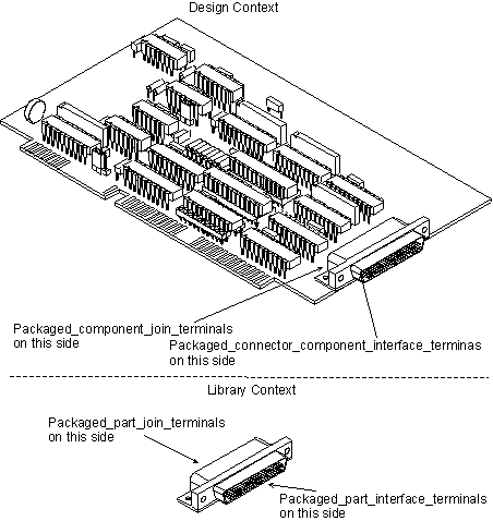
EXAMPLE
Figure 1 illustrates a Packaged_connector and its usage in a design context as a Packaged_connector_component.
Figure 1 — Packaged_connector
EXPRESS specification:
            *)

            ENTITY Packaged_connector

              SUBTYPE OF (Packaged_part);
INVERSE

              characterized_connector_terminal_relationship : SET[1:?] OF Packaged_connector_terminal_relationship FOR connector;

            END_ENTITY;
(*
Attribute definitions:
characterized_connector_terminal_relationship:
an inverse relationship that specifies that the
existence of the Packaged_connector is dependent on
the existence of the Packaged_connector_terminal_relationship that specifies the Packaged_connector as its
connector. There shall be one or more Packaged_connector_terminal_relationship for a
Packaged_connector.
A Packaged_connector_terminal_relationship is the association
between one interface terminal and a corresponding join terminal of the Packaged_connector that specifies that the two terminals are shorted internally to the
Packaged_connector as part of its required functionality. This relationship is an explicit statement of the
inherent functionality of a connector. Therefore no separate Functional_unit_network_definition or Analytical_model_application is required to specify the nominal functionality of a connector.
A Functional_unit_usage_view may be supplied to support mapping the functional design to the connector join terminals.
NOTE 1
One use for this relationship is to specify the short between the terminal that is installed to the printed
circuit assembly and the terminal that provides the access to the outside environment when an occurrence
of Packaged_connector is installed in the assembly.
NOTE 2
Installation into the next higher assembly is not necessary to achieve this relationship.
NOTE 3
There is a member of this relationship populated for every pair of terminals in the Packaged_connector.
EXPRESS specification:
            *)

            ENTITY Packaged_connector_terminal_relationship;


              connector : Packaged_connector;


              join_terminal : Packaged_part_join_terminal;


              interface_terminal : Packaged_part_interface_terminal;
UNIQUE

              UR1: join_terminal;

              UR2: interface_terminal, connector;

            END_ENTITY;
(*
Attribute definitions:
connector:
specifies the Packaged_connector that
has the Package_terminal that are defined to be
shorted by the Packaged_connector_terminal_relationship.
join_terminal:
specifies a role of the Packaged_part_join_terminal for the Packaged_connector_terminal_relationship.
interface_terminal:
specifies a role of the Packaged_part_interface_terminal for the Packaged_connector_terminal_relationship.
Formal propositions:
UR1:
The join_terminal shall be unique within a population of Packaged_connector_terminal_relationships.
UR2:
The combination of the connector and the interface_terminal shall be unique within a population of
Packaged_connector_terminal_relationships.
A Packaged_part_interface_terminal is a type of Packaged_part_terminal that is a terminal of a Packaged_connector. An occurrence of the
Packaged_part_interface_terminal provides access to the functionality of the assembly into which an
occurrence of a Packaged_connector is installed.
EXPRESS specification:
            *)

            ENTITY Packaged_part_interface_terminal

              SUBTYPE OF (Packaged_part_terminal);
DERIVE

              SELF\Part_terminal.interface_or_join_terminal : interface_or_join_terminal_enumeration := interface_terminal;
INVERSE

              external_connector_function : SET[0:?] OF Packaged_connector_terminal_relationship FOR interface_terminal;

            END_ENTITY;
(*
Attribute definitions:
interface_or_join_terminal:
the terminal shall be an
interface_terminal.
external_connector_function:
an inverse relationship that specifies that the existence of the Packaged_part_interface_terminal is
dependent on the existence of the Packaged_connector_terminal_relationship that specifies the
Packaged_part_interface_terminal as its interface_terminal. There may be zero or more Packaged_connector_terminal_relationship for a Packaged_part_interface_terminal.
NOTE
One interface terminal may be connected to several join terminals by members of
Packaged_connector_terminal_relationship.
This subclause specifies the ARM subtype constraint for
this module. The subtype constraint places a constraint on the
possible super-type / subtype instantiations.
The ARM subtype constraint and definition is
specified below.
The
packaged_part_terminal_subtypes
constraint specifies a constraint that applies to instances of
Packaged_part_terminal
and enforces the rule that its subtypes
Packaged_part_interface_terminal and Packaged_part_join_terminal
are exclusive.
EXPRESS specification:
            *)
SUBTYPE_CONSTRAINT packaged_part_terminal_subtypes FOR Packaged_part_terminal;

              ONEOF (Packaged_part_interface_terminal,
         Packaged_part_join_terminal);

            END_SUBTYPE_CONSTRAINT;
(*
         *)

         END_SCHEMA;  -- Packaged_connector_model_arm
(*
© ISO 2018 — All rights reserved


