|
|
Application module:
Fabrication joint |
ISO/TS 10303-1668:2018-11(E)
© ISO
|
This clause specifies the information requirements for the
Fabrication joint
application module. The information requirements are specified as the
Application Reference Model (ARM) of this application module.
NOTE 1 A graphical representation of the information
requirements is given in
Annex C.
NOTE 2 The mapping specification is specified in
5.1. It shows how
the information requirements are met by using common resources and
constructs defined or imported in the MIM schema of this application
module.
This clause defines the information requirements to which implementations shall
conform using the EXPRESS language as defined in ISO 10303-11.
The following begins the
Fabrication_joint_arm
schema and identifies the necessary external references.
EXPRESS specification:
         *)

            SCHEMA Fabrication_joint_arm;
(*
The following EXPRESS interface statements specify the elements
imported from the ARMs of other application modules.
EXPRESS specification:
*)

            USE FROM
            Land_arm;
               --
            ISO/TS 10303-1692
            USE FROM
            Layered_interconnect_module_with_printed_component_design_arm;
               --
            ISO/TS 10303-1700
            REFERENCE FROM
            Support_resource_arm

               --
            ISO/TS 10303-1800
  (bag_to_set);

(*
NOTE 1
The schemas referenced above are specified in the following
part of ISO 10303:
| Land_arm |
ISO/TS 10303-1692 |
| Layered_interconnect_module_with_printed_component_design_arm |
ISO/TS 10303-1700 |
| Support_resource_arm |
ISO/TS 10303-1800 |
NOTE 2
See Annex C,
Figures
C.1and C.2
for a graphical representation of this schema.
This subclause specifies the ARM type
for this application module. The ARM type and
definition is specified below.
The fabricated_feature_select type allows for the designation of the data
types
Component_termination_passage_join_terminal, Conductive_interconnect_element_terminal, Embedded_physical_component_terminal, Land_join_terminal, Printed_component_join_terminal, and Via_terminal.
EXPRESS specification:
            *)

            TYPE
            fabricated_feature_select =


            SELECT

               (Component_termination_passage_join_terminal,
    Conductive_interconnect_element_terminal,
    Embedded_physical_component_terminal,
    Land_join_terminal,
    Printed_component_join_terminal,
    Via_terminal);

            END_TYPE;

            (*
This subclause specifies the ARM entities for this
module. Each ARM application entity is an atomic element that
embodies a unique application concept and contains attributes
specifying the data elements of the entity. The ARM
entities and definitions are specified below.
A Connection_zone_based_fabrication_joint is a type of Fabrication_joint.
A Connection_zone_based_fabrication_joint specializes the definition of Fabrication_joint
by providing additional detail showing specific connection areas on each end of the joint. zone_1 is a connection area on
fabrication_feature_1
and zone_2
is a connection area on
fabrication_feature_2.
NOTE 1
A Connection_zone_based_fabrication_joint is rarely used. Implementation projects should carefully review the source data to validate the implementation requirement
before implementing this
Application Object.
EXPRESS specification:
            *)

            ENTITY Connection_zone_based_fabrication_joint

              SUBTYPE OF (Fabrication_joint);


              zone_1 : Connection_zone_in_design_view;


              zone_2 : Connection_zone_in_design_view;
WHERE

              WR1: zone_1 :<>: zone_2;

            END_ENTITY;
(*
Attribute definitions:
zone_1:
specifies a role of the Connection_zone_in_design_view for the Connection_zone_based_fabrication_joint.
zone_2:
specifies a role of the Connection_zone_in_design_view for the Connection_zone_based_fabrication_joint.
NOTE 2
There are no semantics associated with the sequence of zones in a Connection_zone_based_fabrication_joint.
Formal propositions:
WR1:
The zone_1 shall not be zone_2.
A Fabrication_joint is a type of
Component_feature_joint.
A Fabrication_joint identifies a joint that is created in the fabrication of a printed circuit board.
A Fabrication_joint is usually provided only when it is necessary to state that an intersection of a
Conductive_interconnect_element
and Land includes additional material.
A Fabrication_joint may be used when the preferred method of asserting that a joint exists between a
Land
and a
Conductive_interconnect_element
is unsuitable.
The preferred method of asserting that a joint exists between a
Land
and a
Conductive_interconnect_element
is to populate a member of
Layer_connection_point
at the same location as the
Land
and specify that the
Layer_connection_point
is in the role of location for the
Conductive_interconnect_element_terminal
that is in the role of
access_mechanisms
for the
Conductive_interconnect_element.
NOTE 1
The preferred method of asserting that a joint exists between the
Land
and the
Conductive_interconnect_element
may be unsuitable when the pre-processor uses the end point of the centreline of the
Conductive_interconnect_element
as a location of the
Layer_connection_point
but the centreline of the
Conductive_interconnect_element
does not intersect the
Cartesian_point
associated with the location of the
Land.
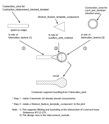
EXAMPLE 1
Figure 1 is a plan view of the construction of a Fabrication_joint between a
Land and a
Conductive_interconnect_element
where both contribute to a Conductor segment. This figure illustrates the geometric relationship of the element terminals in the construction of the segment.
In this example, the Fabrication_joint is provided because auxiliary material intended to increase manufacturability of the local metalization in the area of the
intersection is provided.
Figure 1 — Land to Conductive interconnect element Fabrication_joint exploded view
NOTE 2
The placement of the of the
Conductive_interconnect_element
in Figure 1
is atypical of usual design practice and is provided only for illustrative purposes. Normal design practice with this geometry
would be for the end of the
Conductive_interconnect_element
to be conguent with the center of the
Land.
NOTE 3
A Fabrication_joint may be provided by a pre-processor where there are known accuracy issues regarding the location of
the intersection of a
Conductive_interconnect_element
and a
Land
and it is necessary
to provide auxiliary information that indicates the intent of the designer.
NOTE 4
A Fabrication_joint may be used where there is a need to do a detailed analysis of manufacturing process variations due to use of state of the
art feature size and spacing dimensions.
NOTE 5
Fabrication joint is not a native CAD system concept and must be synthesized as needed by a pre-processor.
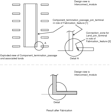
EXAMPLE 2
Figure 2 is a cross-sectional view of the construction of a Fabrication_joint between a
Land and a Component_termination_passage.
Figure 2 — Land to Component termination passage exploded view
EXPRESS specification:
            *)

            ENTITY Fabrication_joint

              SUBTYPE OF (Component_feature_joint);


              SELF\Component_feature_joint.feature_1 RENAMED fabrication_feature_1 : fabricated_feature_select;


              SELF\Component_feature_joint.feature_2 RENAMED fabrication_feature_2 : fabricated_feature_select;


              auxiliary_joint_material :
            OPTIONAL
            Stratum_feature_template_component;


              SELF\Shape_element.associated_definition : Layered_interconnect_module_design_view;
WHERE

              WR1: fabrication_feature_1 <> fabrication_feature_2;

              WR2: TYPEOF(fabrication_feature_1) <> TYPEOF(auxiliary_joint_material);

              WR3: TYPEOF(fabrication_feature_2) <> TYPEOF(auxiliary_joint_material);

            END_ENTITY;
(*
Attribute definitions:
fabrication_feature_1:
specifies one role of the
fabricated_feature_select
for the Fabrication_joint.
fabrication_feature_2:
specifies one role of the
fabricated_feature_select
for the Fabrication_joint.
auxiliary_joint_material:
specifies the role of the
Stratum_feature_template_component
for the Fabrication_joint.
The value of this attribute need not be specified.
associated_definition:
specifies the role of the
Layered_interconnect_module_design_view
for the Fabrication_joint.
Formal propositions:
WR1:
The fabrication_feature_1 shall not be the fabrication_feature_2.
WR2:
The fabrication_feature_1 shall not be the auxiliary_joint_material.
WR3:
The fabrication_feature_2 shall not be the auxiliary_joint_material.
A Passage_terminal_based_fabrication_joint_link is a directed link between two
Fabrication_joint that are associated with a common conductive passage in the interconnect substrate.
A Passage_terminal_based_fabrication_joint_link is provided to support construction of a tree representation of the connection paths in the substrate to support analysis
or synthesis activities.
A Passage_terminal_based_fabrication_joint_link is unnecessary for basic description of the connections in the substrate.
EXPRESS specification:
            *)

            ENTITY Passage_terminal_based_fabrication_joint_link;


              associated_terminal : fabricated_feature_select;


              precedent_point : Fabrication_joint;


              subsequent_point : Fabrication_joint;
UNIQUE

              UR1: associated_terminal, precedent_point, subsequent_point;
WHERE

              WR1: precedent_point <> subsequent_point;

              WR2: precedent_point.fabrication_feature_2 = associated_terminal;

              WR3: subsequent_point.fabrication_feature_1 = associated_terminal;

              WR4: SIZEOF(TYPEOF(associated_terminal) *
            ['LAYERED_INTERCONNECT_MODULE_DESIGN_ARM.' +
            'COMPONENT_TERMINATION_PASSAGE_JOIN_TERMINAL',
            'LAYERED_INTERCONNECT_MODULE_DESIGN_ARM.' +
            'VIA_TERMINAL']) = 1;

              WR5: acyclic_passage_terminal_based_fabrication_joint_link (SELF,
            [subsequent_point],
            'FABRICATION_JOINT_ARM.PASSAGE_TERMINAL_BASED_FABRICATION_JOINT_LINK');

            END_ENTITY;
(*
Attribute definitions:
associated_terminal:
specifies the role of the fabricated_feature_select for the Passage_terminal_based_fabrication_joint_link.
precedent_point:
specifies the role of the Fabrication_joint for the Passage_terminal_based_fabrication_joint_link.
subsequent_point:
specifies the role of the Fabrication_joint for the Passage_terminal_based_fabrication_joint_link.
Formal propositions:
UR1:
The combination of associated_terminal, precedent_point and subsequent_point shall be unique within a population of Passage_terminal_based_fabrication_joint_link.
WR1:
The precedent_point shall not be the subsequent_point.
WR2:
The terminal referenced by the fabrication_feature_2 attribute of the Fabrication_joint referenced by
precedent_point shall be the terminal referenced by associated_terminal.
WR3:
The terminal referenced by the fabrication_feature_1 attribute of the Fabrication_joint referenced by
subsequent_point shall be the terminal referenced by associated_terminal.
WR4:
The associated_terminal shall only be of type Component_termination_passage_join_terminal,
or of type Via_terminal.
WR5:
The graph of instances of the Application Object Passage_terminal_based_fabrication_joint_link shall not contain a cycle.
This subclause specifies the ARM function for
this module. The ARM function and definition is
specified below.
The acyclic_passage_terminal_based_fabrication_joint_link function determines
whether the graph of instances of the Application Object type
Passage_terminal_based_fabrication_joint_link
that contains relation as one of its links contains a cycle.
This function may be used to evaluate
Passage_terminal_based_fabrication_joint_link
or any of it's subtypes.
EXPRESS specification:
         *)

         FUNCTION acyclic_passage_terminal_based_fabrication_joint_link (relation : Passage_terminal_based_fabrication_joint_link; relatives : SET[1:?] OF Fabrication_joint; specific_relation : STRING) : BOOLEAN;
LOCAL
       x : SET OF Passage_terminal_based_fabrication_joint_link;
     END_LOCAL;

     IF relation.precedent_point IN relatives THEN
       RETURN (FALSE);
     END_IF;
     x := QUERY(pd <* bag_to_set(USEDIN(relation.precedent_point,
       'FABRICATION_JOINT_ARM.' + 'PASSAGE_TERMINAL_BASED_FABRICATION_JOINT_LINK.' +
       'SUBSEQUENT_POINT')) | specific_relation IN TYPEOF(pd));
     REPEAT i := 1 TO HIINDEX(x);
       IF NOT acyclic_passage_terminal_based_fabrication_joint_link(x[i],
         relatives + relation.precedent_point, specific_relation) THEN
         RETURN (FALSE);
       END_IF;
     END_REPEAT;
   RETURN (TRUE);
         END_FUNCTION;

(*
Argument definitions:
relation:
the specified
Passage_terminal_based_fabrication_joint_link.
relatives:
the specified set of
Fabrication_joint.
specific_relation:
the specified STRING.
         *)

         END_SCHEMA;  -- Fabrication_joint_arm
(*
© ISO 2018 — All rights reserved


